Workstation 5A Setup Guide - Fourth Edition B-9
Connector and Cable Diagrams
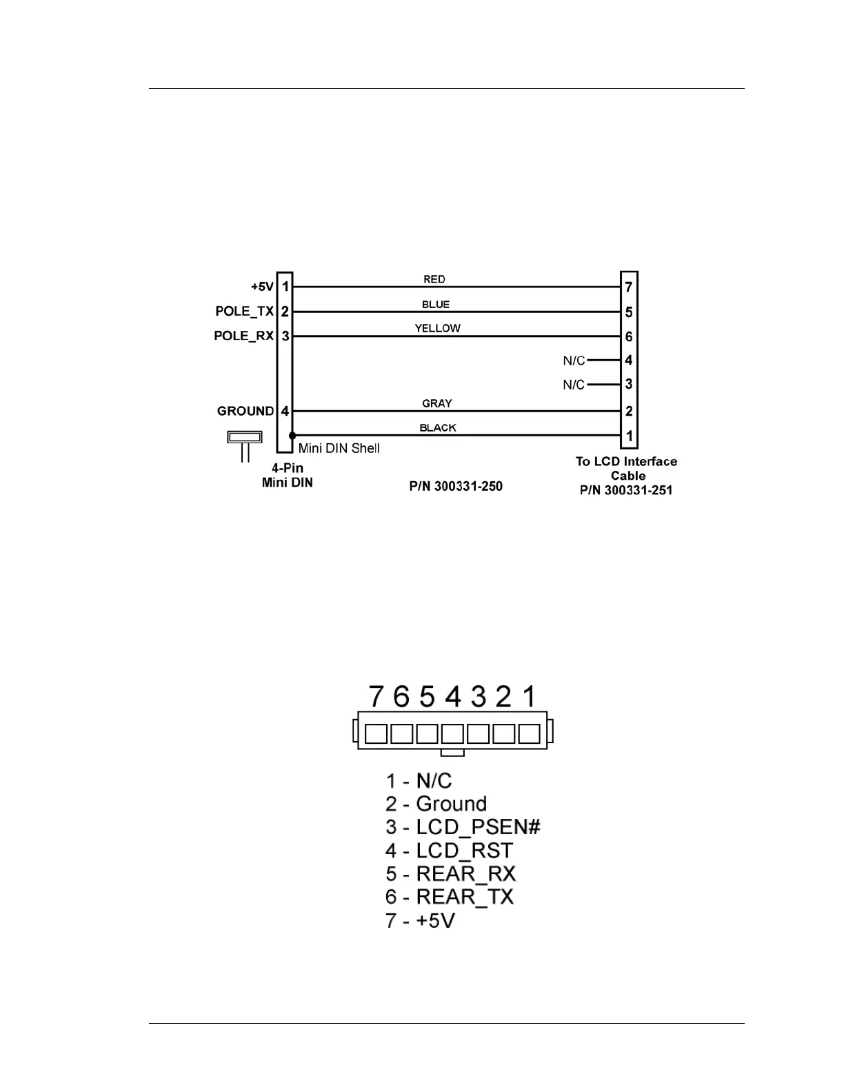
Hook-up Cables
Remote Pole LCD Customer Display
The cable shown in Figure B-12 is supplied with the Pole LCD Customer
Display or Adjustable Stand Pole Display kit. It attaches between the 4-pin
Mini-DIN connector on the Workstation 5A I/O panel, through the pole to
mate with the cable from the LCD Customer Display Housing Cable shown in
Figure B-11.
Figure B-12: Remote Pole LCD Customer Display Assembly
IO Panel LCD Customer Display Connector
The Workstation 5 and 5A places the integrated customer display connector on
the IO Panel. It should not be used for the Protégé Customer Display. A
diagram of this connector is shown below.
Figure B-13: IO Panel Integrated LCD Connector
 Loading...