B-4 Workstation 5A Setup Guide - Fourth Edition
Connector and Cable Diagrams
IO Panel Connectors
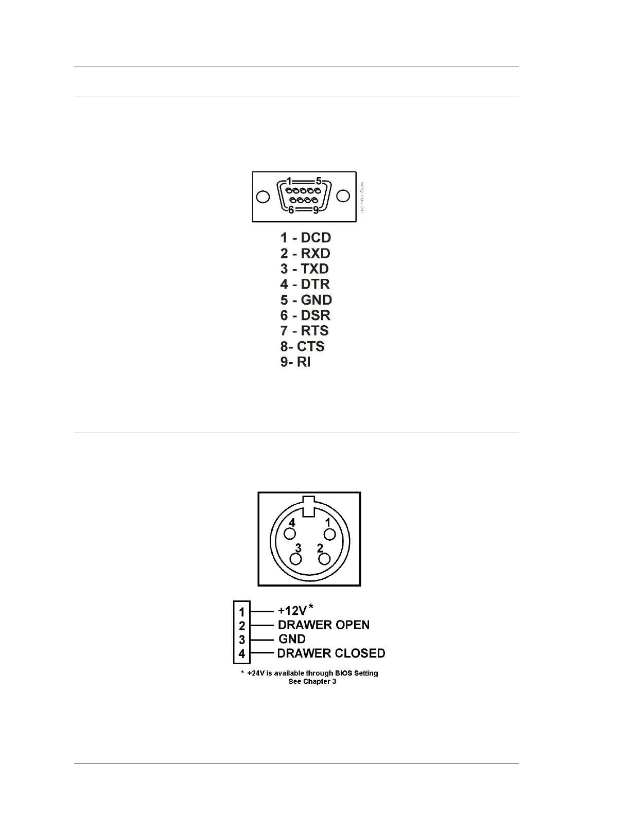
RS232 Connector
A single DB9F RS232 connector assigned to COM1 is provided. The pin-out is
shown below.
Figure B-4: DB9 RS232 Connector Diagram
Cash Drawer 1 and 2 Connectors
Figure B-5: Cash Drawer Connector Diagram
 Loading...