Handbook
November 2011 / 59-UMC0071 / Issue 01
Mercury iTC
Page 67
FUNCTIONAL DESCRIPTION
Original Instructions
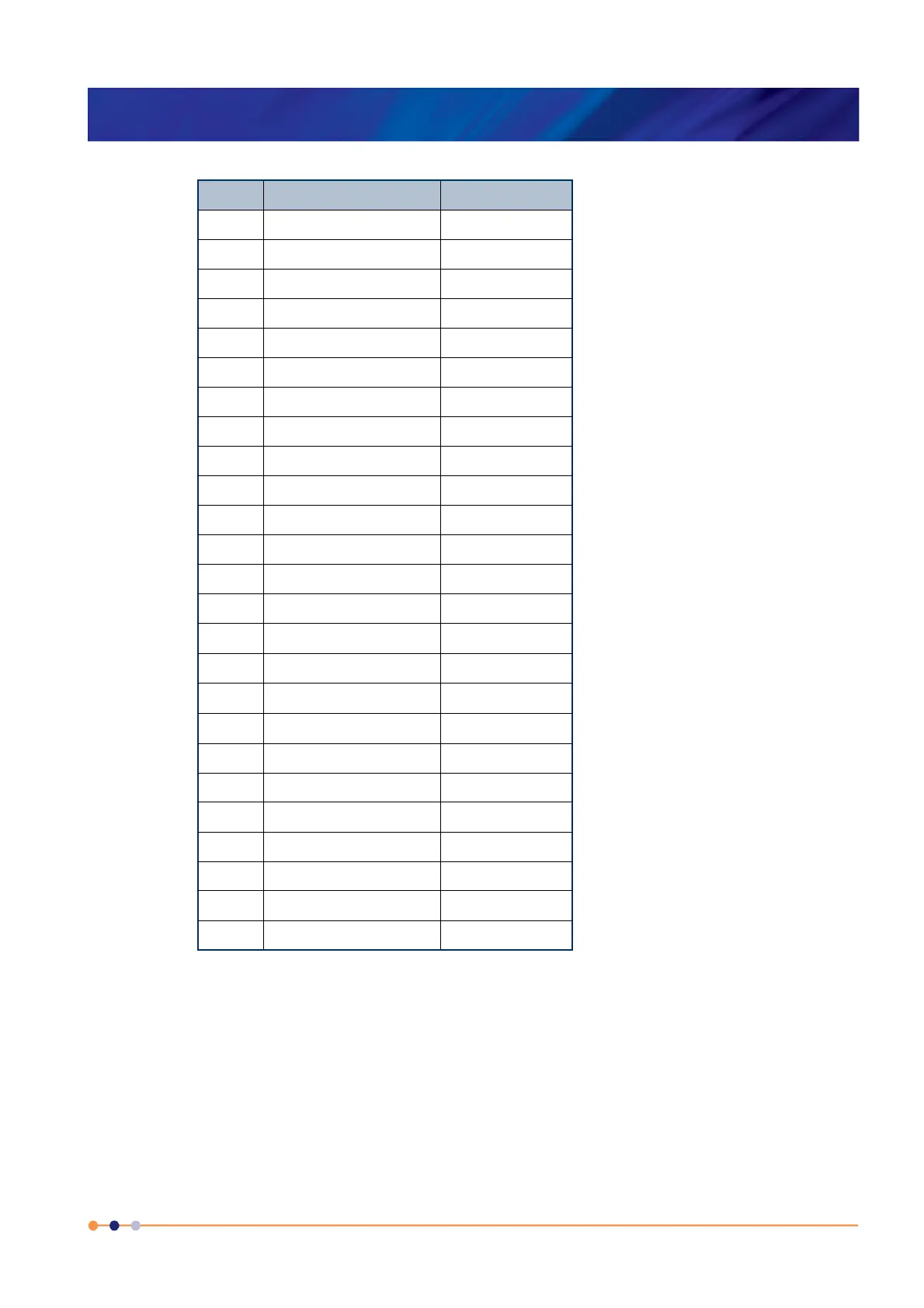
TG 5 AuFe 0.03/Chr 2 to 500K
TG_57 AuFe 0.07/Chr 2 to 500K
TG_57 AuFe 0.07/Chr 2 to 500K
TG_57 AuFe 0.07/Chr 2 to 500K
CN 3 Cernox resistor 1.5 to 300K
TT 5 Copper/Const 20 to 500K
TT 5 Copper/Const 20 to 500K
TT 4 Copper/Const -250 to 400°C
TT 4 Copper/Const -250 to 400°C
TK 10 Chromel/Alumel 0 to 1000°C
TK 10 Chromel/Alumel 0 to 1000°C
TK 13 Chromel/Alumel -200 to 1370°C
TK 13 Chromel/Alumel -200 to 1370°C
CR 11 Ruthenium oxide 0.25 to 10K
RF 52
2
RhFe resistor 1.5 to 500K
RP 1 Platinum resistor -200 to +100°C
RP 5
3
Platinum resistor 20 to 500K
RP 51
4
Platinum resistor 50 to 500K
RL 3 CLTS 2 to 300K
DS 32 Silicon diode (OI) 2 to 300K
DS 31 Silicon diode (LS) 2 to 300K
CC 35 C-glass CR500 2 to 300K
CA 21 100R Allen Bradley 4 to 250K
CA 22 270R Allen Bradley 4 to 250K
CS 01 470R Speer 0.25 to 9.999K
1. The Lin and Null ranges are general purpose ranges that
may be configured for any required span and zero. Both
ranges provide a linear relationship between input and
display. The Lin range is unipolar while the Null range is
bipolar.
2. The iTC includes two curves for 27 Ohm Rhodium/Iron
sensors. Curve A is used for sensors having a resistance of
2 Ohms or greater at 4.2K. Curve B is used for sensors
having a resistance of less than 2 Ohms at 4.2K. Using the
appropriate curve should produce linearisation errors of
less than 1% over the full temperature range. For a more
accurate fit to a specific sensor, order a custom calibration.
3. This is for a pure platinum element.
Table 4-6 Sensor range data
Code Sensor Range
 Loading...