Handbook
November 2011 / 59-UMC0071 / Issue 01
Mercury iTC
Page 128
TEMPERATURE SENSOR DAUGHTER BOARD
Original Instructions
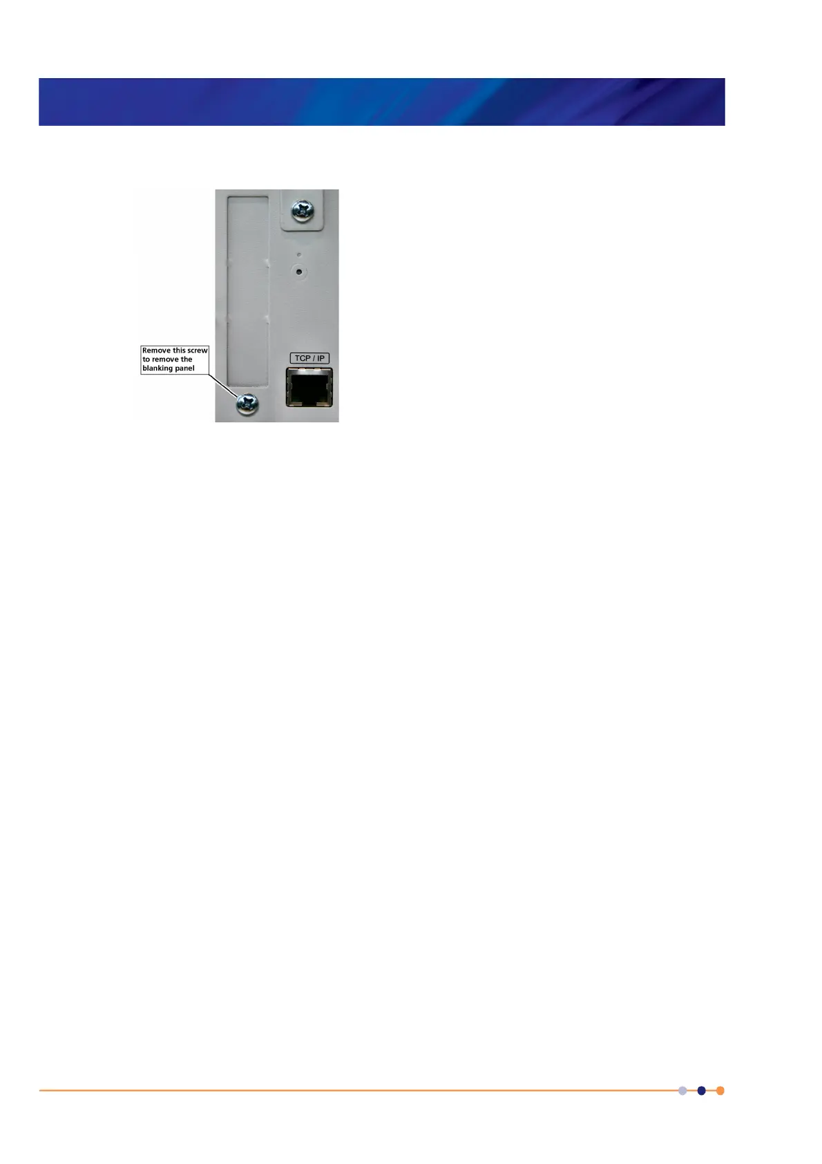
6 Remove the screw that secures the blanking panel in the location where the board
is to be fitted. Keep the screw.
Figure 13-2 Daughter-board blanking-panel
7 Using appropriate ESD precautions, fit the temperature board in the allocated
expansion slot.
8 Secure the board using the screw that was removed in step 6.
9 Refit the board-clamp, using the two screws that were removed earlier.
10 If a heater board is to be installed at the same time, fit the heater board in the
allocated slot.
11 Fit the lid back onto the unit, using the screws that were removed earlier.
13.2.2 Connecting the sensor
A single-sensor board has a single 9-way D-connector.
13.2.3 Configuring the temperature sensor board
See Section 5.4.2 for details.
 Loading...