Handbook
November 2011 / 59-UMC0071 / Issue 01
Mercury iTC
Page 70
FUNCTIONAL DESCRIPTION
Original Instructions
The sensor voltage is:
Vsensor= Vref x ADCnorm/ADCgain
Where:
ADCnorm is the ADC reading normalised to the range 0 to ±1 V.
ADCgain is the gain setting of the ADC.
The temperature of the sensor to heater connection is measured for thermocouple
correction.
If an excitation current is not required (i.e. for a thermocouple sensor), U10 and U15 are
switched off.
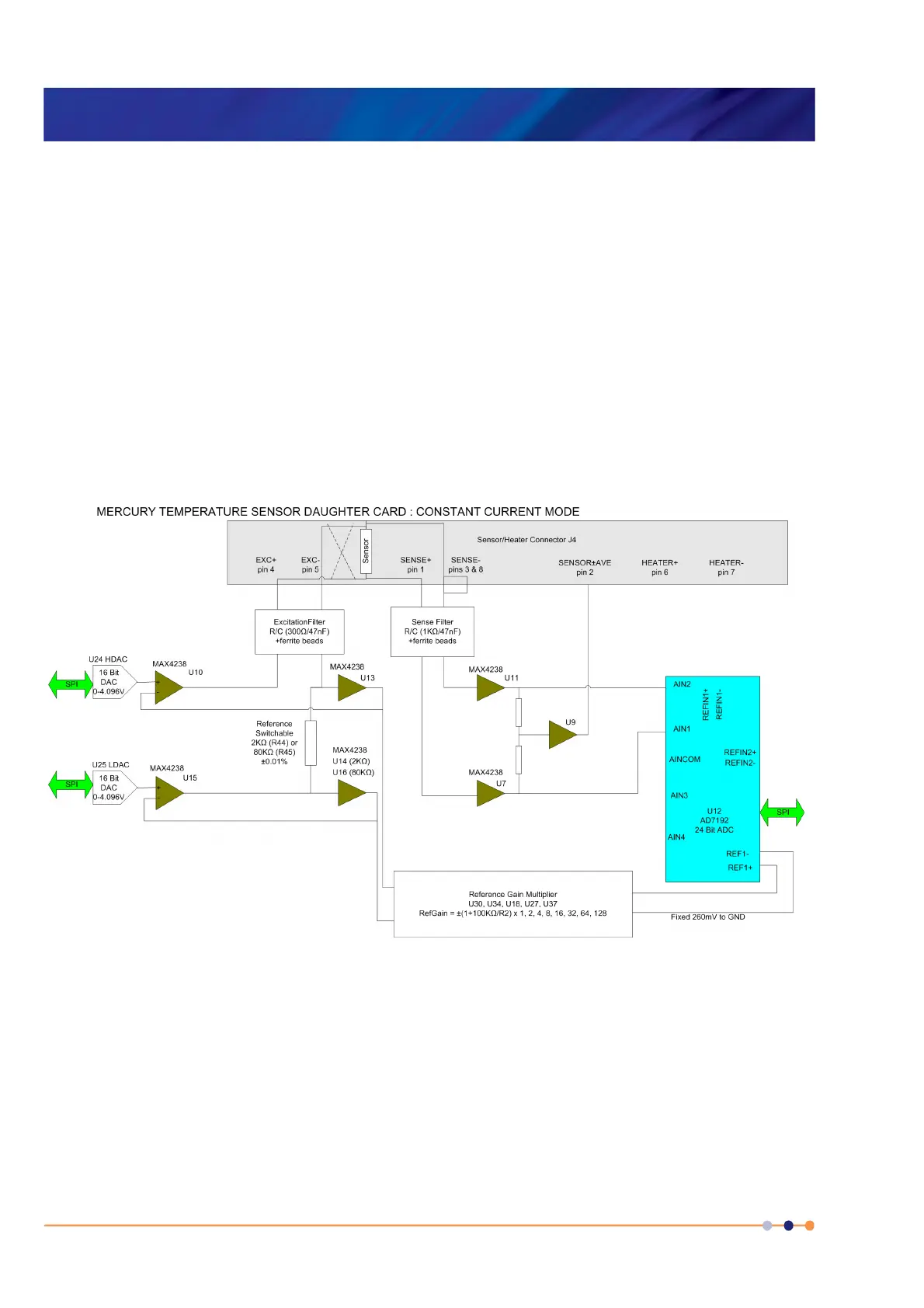
4.6.1.2 Description of constant current measurement mode
Constant current measurement mode is used with sensors that have a positive
temperature coefficient.
Figure 4-4 Block diagram of constant current measurement mode
The sensor and a reference resistor (either R44 or R45) are connected in series. Digital
to analogue converters (DACs) U24 and U25 generate an upper and lower demand
voltage. This voltage is equal to the required current multiplied by the value of the
selected reference resistor.
The upper voltage is buffered by U10 and applied to the upper end of the sensor
resistor. The lower voltage is buffered by U15 and applied to the lower end of the
reference resistor. The same current thus passes through the sensor and the reference
resistor.
 Loading...