Handbook
November 2011 / 59-UMC0071 / Issue 01
Mercury iTC
Page 137
LEVEL-METER DAUGHTER BOARD
Original Instructions
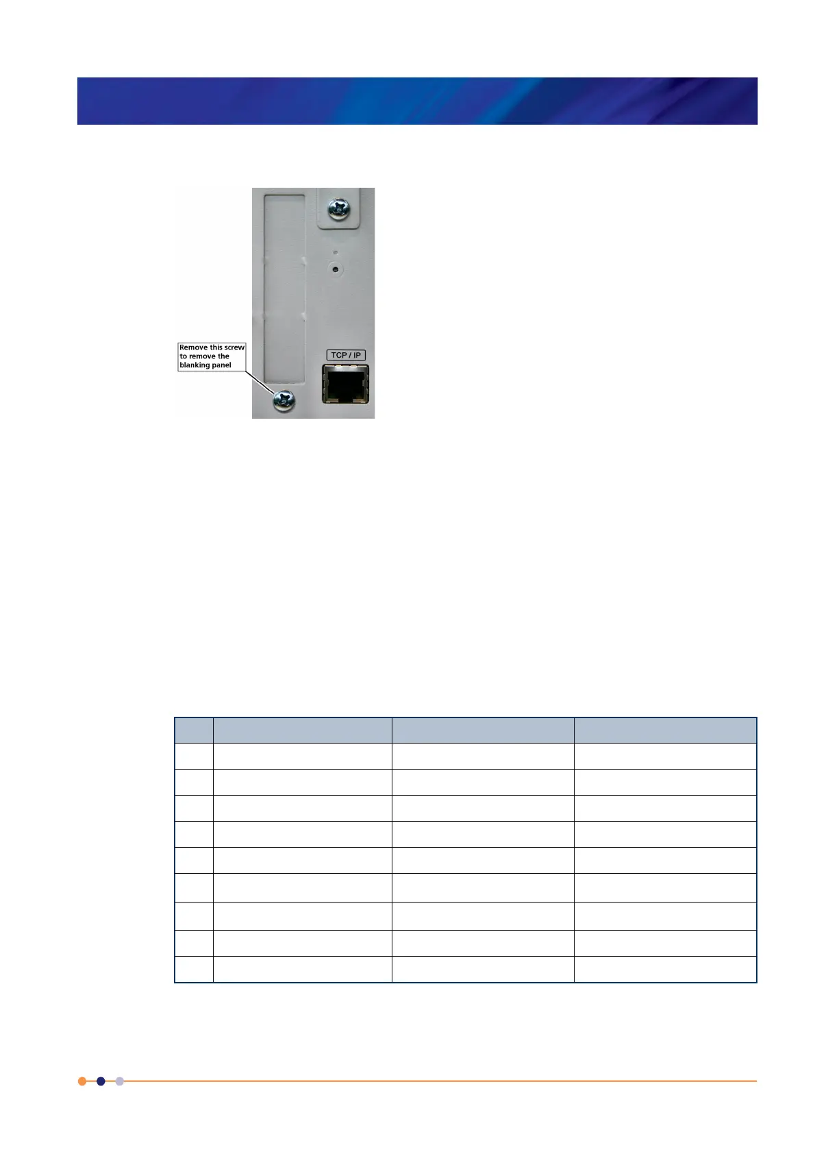
6 Remove the screw that secures the blanking panel in the location where the board
is to be fitted. Keep the screw.
Figure 16-2 Daughter-board blanking-panel
7 Using appropriate ESD precautions, fit the level-meter board in the allocated
expansion slot.
8 Secure the board using the screw that was removed in step 6.
9 Refit the board-clamp, using the two screws that were removed earlier.
10 Fit the lid back onto the unit, using the screws that were removed earlier.
16.2.2 Connecting the sensor
Connect the sensor to the appropriate 9-way D-connector on the rear panel of the
board. The pin connections are listed in Table 16-1.
Table 16-1 Level-meter sensor pin connections
Pin Signal Name Helium Probe Nitrogen Probe
1 VHIGH V sense (Top) n/c
2 VLOW V sense (Bottom) n/c
3 (Unused)
4 FREQ IN Link to 5 OUTPUT FREQ (0 to 12 V)
5 FREQ OUT Link to 4 n/c
6I
HIGH
I (Top) n/c
7I
LOW
I (Bottom) 0 V
8 +12 V n/c +12V (20 mA maximum
9 CHASSIS GND Screen Screen
 Loading...