
R
Ryan WhiteAug 5, 2025
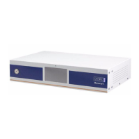
Why doesn't the remote interface work on my Oxford Instruments Mercury iTC Controller?
- SsolistimothyAug 5, 2025
If a remote interface isn’t working on your Oxford Instruments Controller, first, ensure the interface is enabled via the General Settings page. Then, verify all interface connections are secure. Also, confirm the interface settings on the appropriate Settings page are correct. Finally, check that the ISOBUS or GPIB address doesn't conflict with another instrument on the bus.