Handbook
November 2011 / 59-UMC0071 / Issue 01
Mercury iTC
Page 132
AUXILIARY I/O DAUGHTER BOARD
Original Instructions
15.2 Installing an auxiliary I/O board
15.2.1 Fitting the board
An auxiliary I/O board can be fitted in any expansion slot.
1 Turn off electrical power to the iTC.
2 Remove the electrical power connector from the back of the unit.
3 Remove the screws that secure the lid of the iTC. There are 6 screws on either side
panel of the iTC and 3 screws on the rear panel.
4 Lift off the lid.
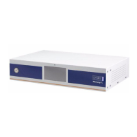
5 Remove the two screws that secure the board-clamp. Remove the board clamp.
Figure 15-1 Board-clamp
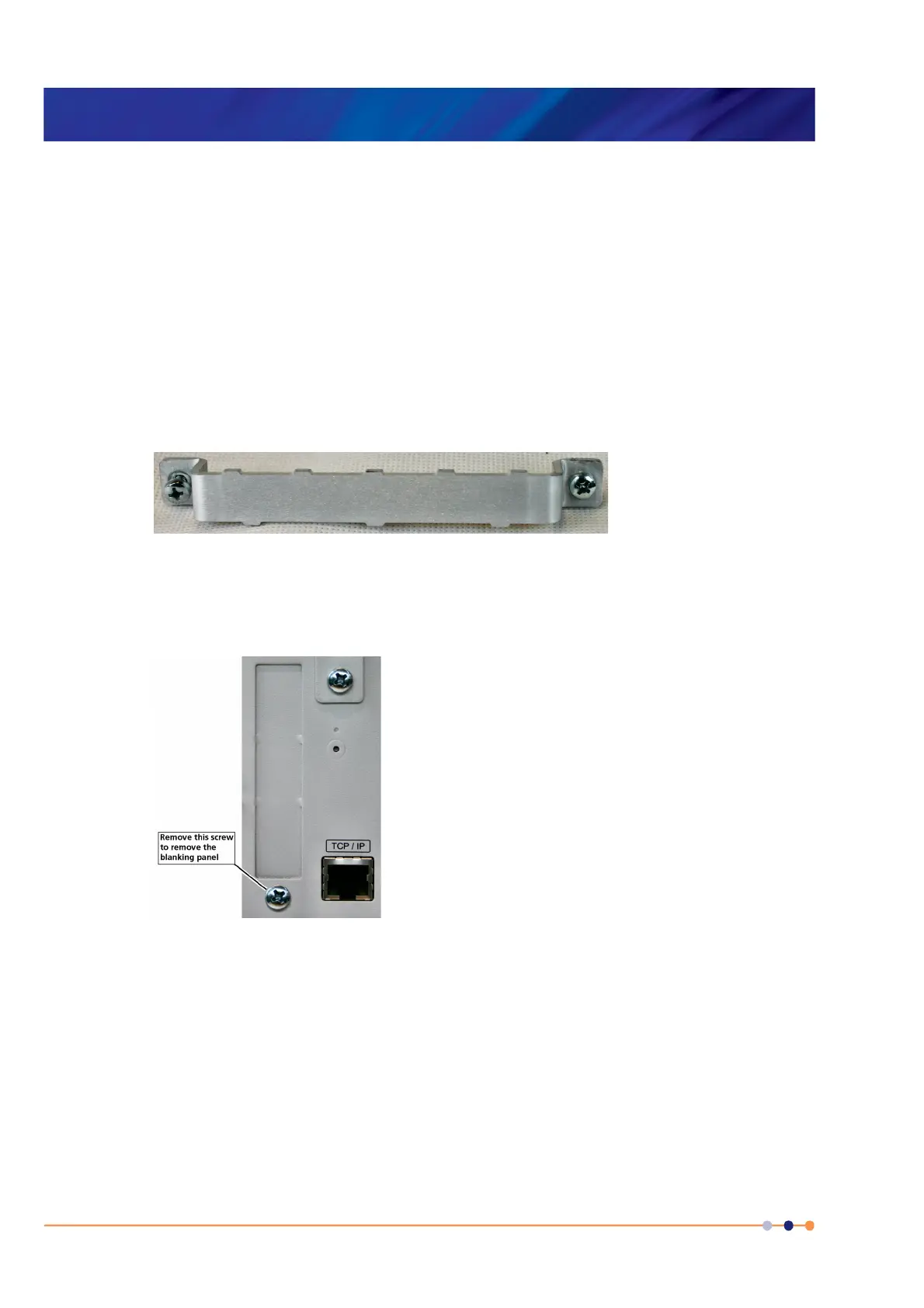
6 Remove the screw that secures the blanking panel in the location where the board
is to be fitted. Keep the screw.
Figure 15-2 Daughter-board blanking-panel
7 Using appropriate ESD precautions, fit the auxiliary I/O board in the allocated
expansion slot.
8 Secure the board using the screw that was removed in step 6.
9 Refit the board-clamp, using the two screws that were removed earlier.
10 Fit the lid back onto the unit, using the screws that were removed earlier.
 Loading...