Specifications
FP0
12 − 8
12.2 I/O Allocation Table
12.2 I/O Allocation Table
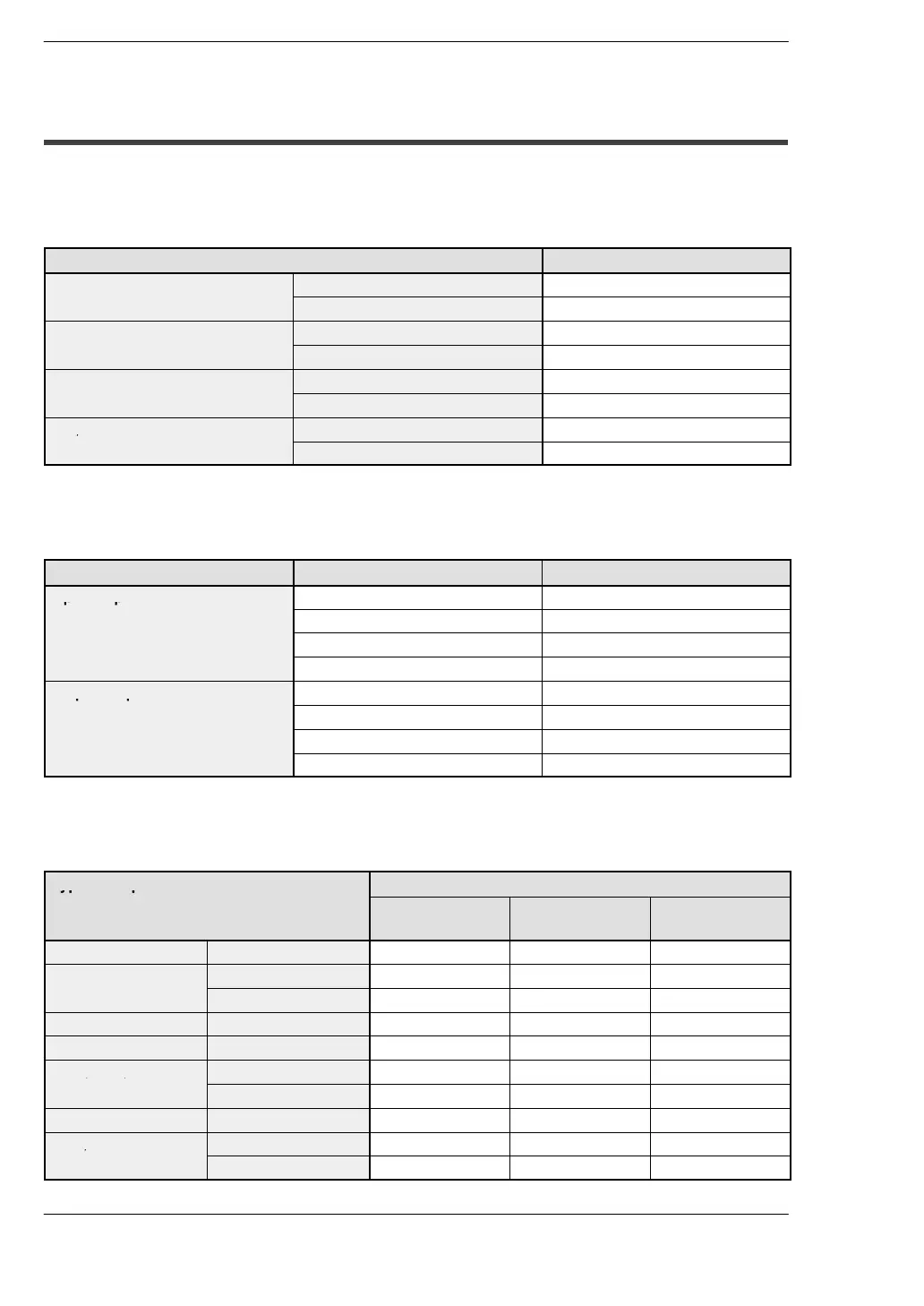
FP0 Control Units
The I/O allocation of the FP0 control unit is fixed.
Type of Control Unit I/O number
C10 series
Input: 6 points X0 to X5
Output: 4 points Y0 to Y3
C14 series
Input: 8 points X0 to X7
Output: 6 points Y0 to Y5
C16 series
Input: 8 points X0 to X7
Output: 8 points Y0 to Y7
C32/T32 series
Input: 16 points X0 to XF
Output: 16 points Y0 to YF
S−LINK Control Units
The I/O allocation of the S−LINK control unit is fixed.
Unit FP0 I/O S−LINK address
Input: 64 points
X80 to X8F 0to15
X90 to X9F 16 to 31
X100 to X10F 32 to 47
X110 to X11F 48 to 63
Output: 64 points
Y80 to Y8F 64 to 79
Y90 to Y9F 80 to 95
Y100 to Y10F 96 to 111
Y110 to Y11F 112 to 127
FP0 Expansion Units
The I/O allocation of the FP0 expansion unit is determined by order of connection.
Type of Expansion Unit
I/O number
First expansion Second
expansion
Third expansion
E8X Input: 8 points X20 to X27 X40 to X47 X60 to X67
E8R
Input: 4 points X20 to X23 X40 to X43 X60 to X63
Output: 4 points Y20 to Y23 Y40 to Y43 Y60 to Y63
E8YR/E8YT/E8YP Output: 8 points Y20 to Y27 Y40 to Y47 Y60 to Y67
E16X Input: 16 points X20 to X2F X40 to X4F X60 to X6F
E16R/E16T/E16P
Input: 8 points X20 to X27 X40 to X47 X60 to X67
Output: 8 points Y20 to Y27 Y40 to Y47 Y60 to Y67
E16YT/E16YP Output: 16 points Y20 to Y2F Y40 to Y4F Y60 to Y6F
E32T/E32P
Input: 16 points X20 to X2F X40 to X4F X60 to X6F
Output: 16 points Y20 to Y2F Y40 to Y4F Y60 to Y6F