Specifications
FP0
12 − 9
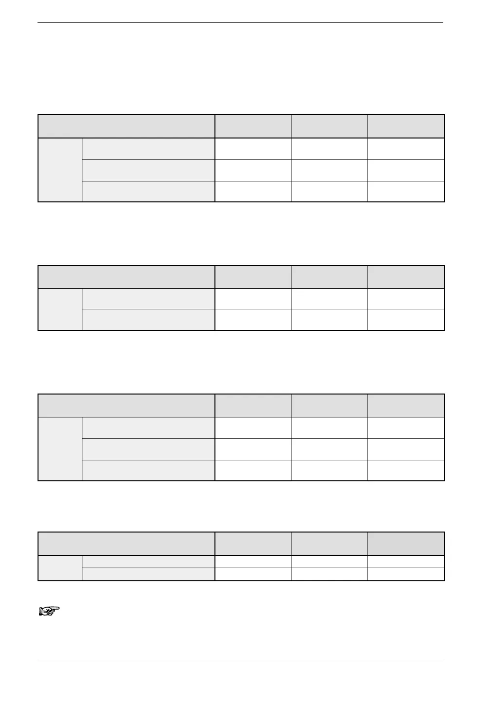
12.2 I/O Allocation Table
Analog I/O Unit
The I/O allocations of the analog I/O unit are determined by the position at which the unit
is installed.
Type First expansion Second
expansion
Third expansion
A21
Input: CH0 16 points WX2
(X20 to X2F)
WX4
(X40 to X4F)
WX6
(X60 to X6F)
Input: CH1 16 points WX3
(X30 to X3F)
WX5
(X50 to X5F)
WX7
(X70 to X7F)
Output: 16 points WY2
(Y20 to Y2F)
WY4
(Y40 to Y4F)
WY6
(Y60 to Y6F)
A/D Converter Unit and Thermocouple Unit
The data of each channel switches and then reads or writes by the user program which
contains the conversion data switch flag.
Type First expansion Second
expansion
Third expansion
A80,
Input: CH0, 2, 4, 6
16 points
WX2
(X20 to X2F)
WX4
(X40 to X4F)
WX6
(X60 to X6F)
,
TC8
Input: CH1, 3, 5, 7
16 points
WX3
(X30 to X3F)
WX5
(X50 to X5F)
WX7
(X70 to X7F)
D/A Converter Unit
The data of each channel switches and then reads or writes by the user program which
contains the conversion data switch flag.
Type First expansion Second
expansion
Third expansion
A04V
Input: 16 points WX2
(X20 to X2F)
WX4
(X40 to X4F)
WX6
(X60 to X6F)
Output: CH0, 2, 4, 6
16 points
WY2
(Y20 to Y2F)
WY4
(Y40 to Y4F)
WY6
(Y60 to Y6F)
Output: CH1, 3, 5, 7
16 points
WY3
(Y30 to Y3F)
WY5
(Y50 to Y5F)
WY7
(Y70 to Y7F)
I/O Link Unit
The I/O allocation of the I/O link unit is determined by order of connection.
Type First expansion Second
expansion
Third expansion
IOL
Input: 32 points
X20 to
3F
40 to
5F
60 to X7F
output: 32 points Y20 to Y3F Y40 to Y5F Y60 to Y7F
Note
Please verify with the manual for the FP0 CC−Link slave unit.