14-6
2. Hold types and non-hold type settings (System registers 6 to 8 and 14)
With the FP0 C10/C14/C16/C32/SL1, the areas held in the event of a power supply interruption are fixed
at the areas shown in the table below, and the settings for system registers 6 to 8 and 14, will be invalid.
C10/C14/C16
Timer Non-hold type: All points
Non-hold type: From the set value to C139
Counter
Hold type: 4 points (elapsed values )C140 to C143
Non-hold type:
976 points (R0 to R60F)
61 words (WR0 to WR60)
Internal relay
Hold type:
32 points (R610 to R62F)
2 words (WR61 to WR62)
Non-hold type: 1652 words (DT0 to DT1651)
Data register
Hold type: 8 words (DT1652 to DT1659)
C32/SL1
Timer Non-hold type: All points
Non-hold type: From the set value to C127
Counter
Hold type: 16 points (elapsed values )C128 to C143
Non-hold type:
880 points (R0 to R54F)
55 words (WR0 to WR54
Internal relay
Hold type:
128 points (R550 to R62F)
8 words (WR55 to WR62)
Non-hold type: 6112 words (DT0 to DT6111)
Data register
Hold type: 32 words (DT6112 to DT6143)
With the FP0 T32, set each relay and register to a hold type or non-hold type.
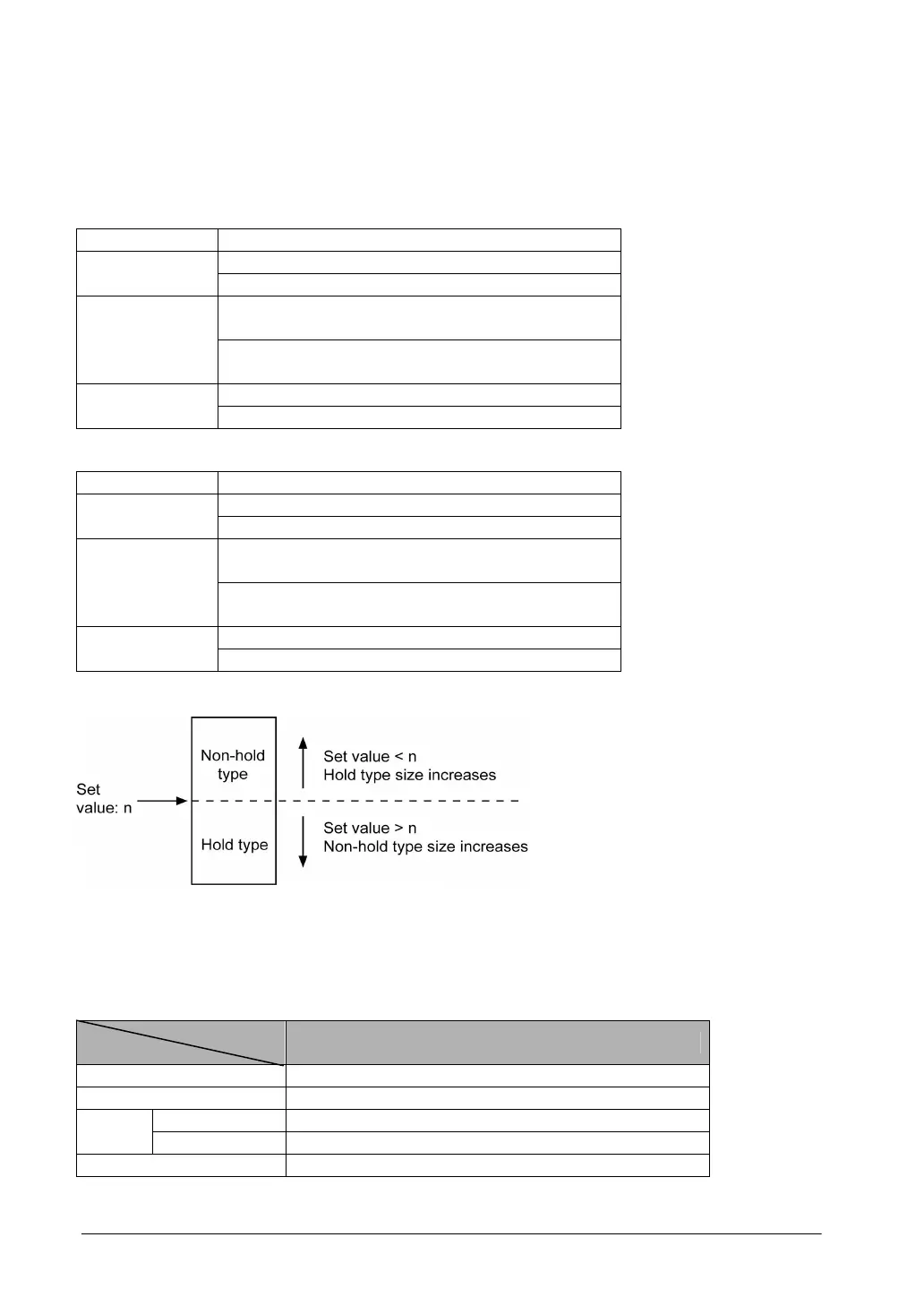
For normal situations, set the system registers 5 and 6 to the same value. This sets the timer to a non-
hold type and counter to a hold type.
By setting this value to “0”, the whole area becomes hold type. Also, by setting it to the valeu 1 higher
than the last number, the whold area becomes non-hold type.
C32/SL1
Type
Area
FP0 T32
Timer All non-hold type
Counter All hold type
Non-hold type Non-hold type: 10 words (WR0 to WR9) Internal
relay
Hold type Hold type: 53 words (WR10 to WR62)
Data register All hold type