14-7
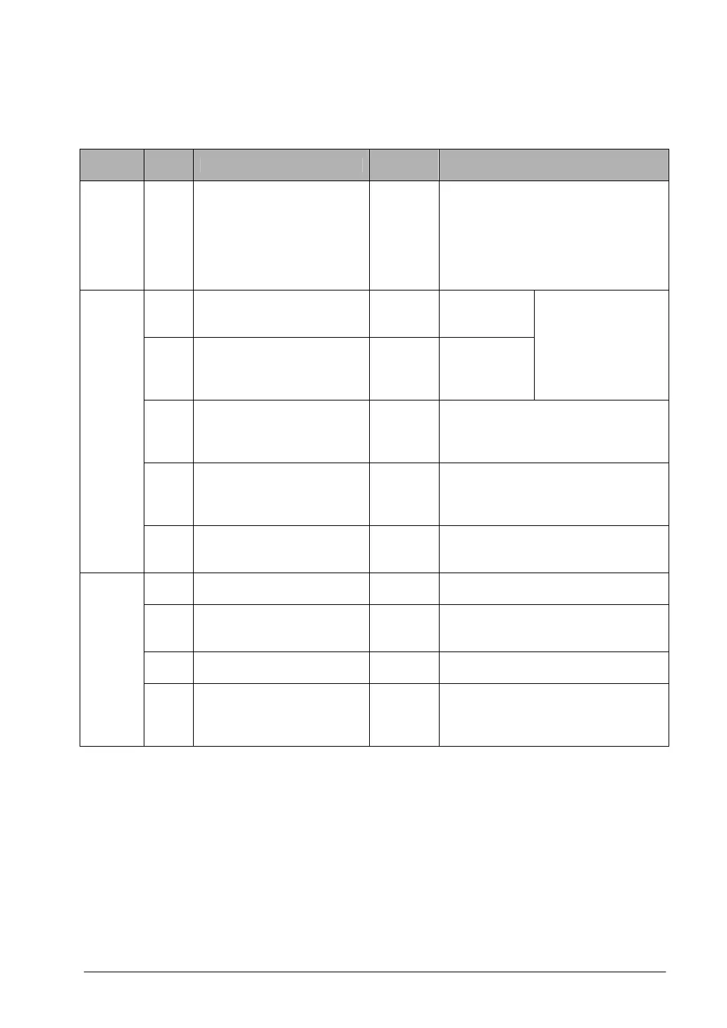
Table of system registers
C10, C14, C16, C32, T32 and SL1 in the table respectively indicate 10-point, 14-point, 16-point, 32-point
type and S-LINK type FP0 control units.
Item
Add-
ress
Name
Default
value
Descriptions
Alloca-
tion of
user
memory
0
Sequence program area
capacity
-
The set values are fixed and cannot
be changed.
The stored values vary depending on
the type.
K3: 3K words (FP0 C10, C14, C16)
K5: 5K words (FP0 C32, SL1)
K10: 10K words (FP0 T32)
5
Timer and counter
division (setting of
starting counter number)
100
(K100)
0 to 144
(K0 to K144)
6
Hold type area starting
number setting for timer
and counter
(Available type: T32)
100
(K100)
0 to 144
(K0 to K144)
Set the system
registers 5 and 6 to
the same value.
7
Hold type area starting
number setting for internal
relays (in word units)
(Available type: T32)
10
(K10)
0 to 63 (K0 to K63)
8
Hold type area starting
number setting for data
registers
(Available type: T32)
0
(K0)
0 to 16384 (K0 to K16384)
Hold/
Non-
hold
14
Hold or non-hold setting
for step ladder process
(Available type: T32)
Non-hold
(K1)
Hold (K10)
Non-hold (K1)
20
Disable or enable setting
for duplicated output
Disable
(K0)
Disable (will be syntax error) (K0)
Enable (will not be syntax error) (K1)
23
Operation setting when an
I/O verification error
occurs
Stop
(K0)
Stop (K0)
Operate (K1)
26
Operation setting when an
operation error occurs
Stop
(K0)
Stop (K0)
Operate (K1)
Action
on error
27
Operation settings when
communication error
occurs in the remote I/O
(S-LINK) system
Operate
(K1)
Stop (K0)
Operate (K1)
Note) The setting values of the system registers No. 6, 7, 8 and 14 becomes invalid with the types other
than T32.