Optional Memory FP0
2 − 18
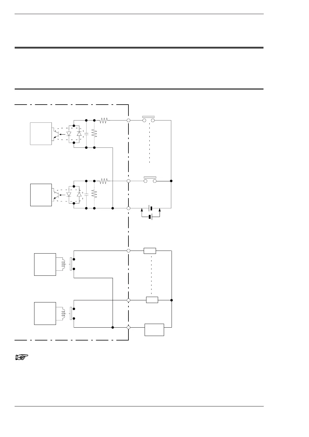
2.3 Internal Circuit Diagram
2.3 Internal Circuit Diagram
2.3.1 Relay Output Type
(C10RS/C10CRS/C10RM/C10CRM/C14RS/C14CRS/C14RM/C14CRM)
FP0-C10RS/C10CRS/C10RM/C10CRM/C14RS/C14CRS/C14RM/C14CRM
Internal
circuit
X0
Xn
COM
Y0
Yn
COM
Power
supply
Input side
Output side
5.6 kΩ
(* Note 1)
5.6 kΩ
Internal
circuit
Internal
circuit
Internal
circuit
Load
Load
(* No te
1)
24 V DC (* Note 2)
Notes
1) The resistor in the control unit is 2 kΩ for X0 through X5, and 1
kΩ for X6 and X7.
2) Either positive or negative polarity is possible for the input
voltage supply.