1-92 Programming Your Application
690+ Series Frequency Inverter
Functional Description
Installation Product Manual, Chapter 4: “Operating the Inverter” - Starting and Stopping
Methods, describes the use of the system ramp.
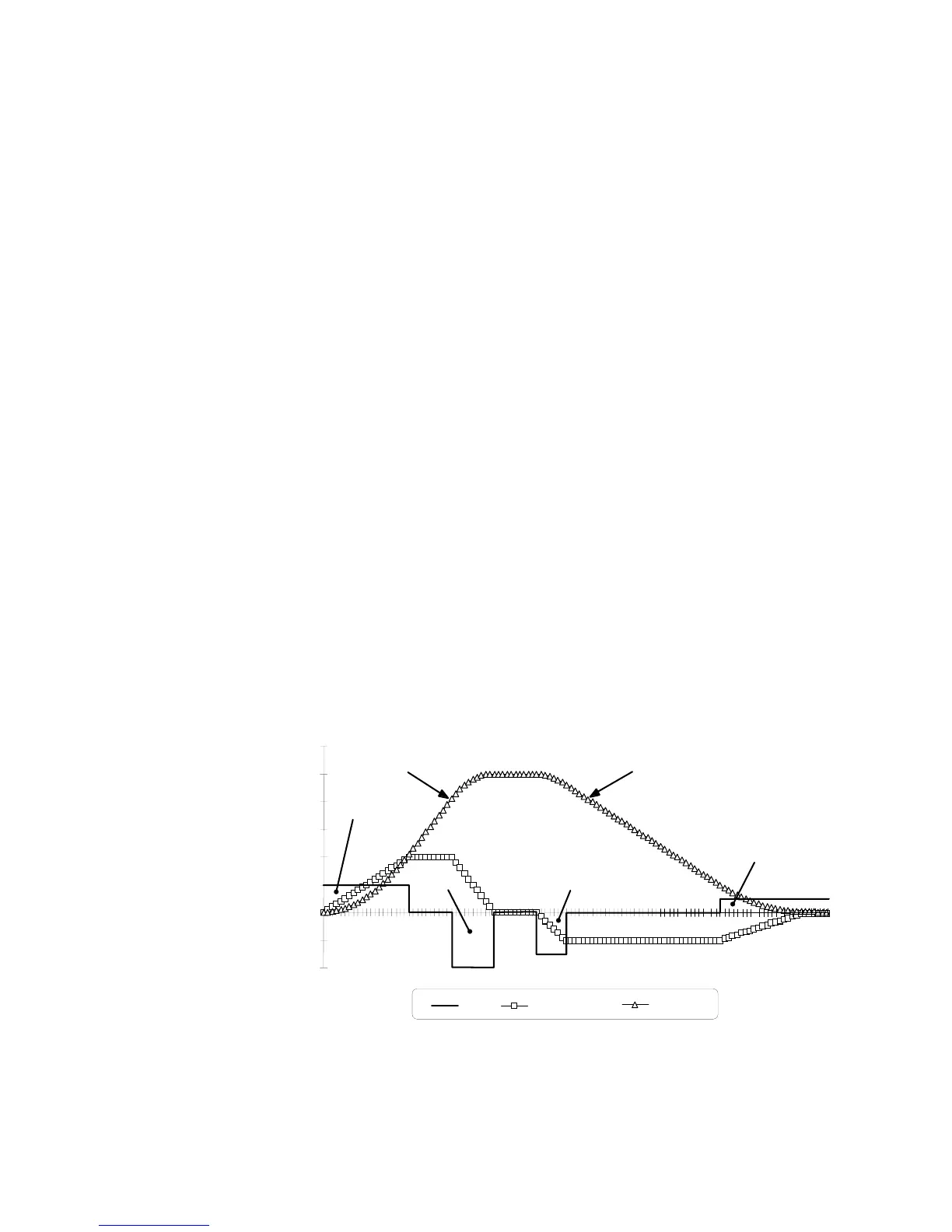
The ramp output takes the form shown below.
S-Ramp
-20
-10
0
10
20
30
40
50
60
Time (secs)
%
Jerk Acceleration Velocity
Jerk 3
Jerk 4
Jerk 2
Jerk 1
Acceleration
Deceleration
Parameter Descriptions
SRAMP JERK 1
Range: 0.00 to 100.00 /s
3
Rate of change of acceleration for the first segment of the curve in units per second³, i.e. if the
full speed of the machine is 1.25m/s then the acceleration will be:
1.25 x 50.00% = 0.625m/s³
SRAMP JERK 2
Range: 0.00 to 100.00 /s
3
Rate of change of acceleration in units of percent per second³ for segment 2.
SRAMP JERK 3
Range: 0.00 to 100.00 /s
3
Rate of change of acceleration in units of percent per second³ for segment 3.
SRAMP JERK 4
Range: 0.00 to 100.00 /s
3
Rate of change of acceleration in units of percent per second³ for segment 4.
SRAMP CONTINUOUS
Range: FALSE / TRUE
When TRUE, and S ramp is selected in RAMP TYPE, forces a smooth transition if the speed
setpoint is changed when ramping. The curve is controlled by the SRAMP ACCEL and
SRAMP JERK 1 to SRAMP JERK 4 parameters. When FALSE, there is an immediate
transition from the old curve to the new curve.
RAMP HOLD
Range: FALSE / TRUE
When TRUE the output of the ramp is held at its last value.
RAMPING
Range: FALSE / TRUE
Set TRUE when ramping.

 Loading...


