Setting up Compax3
C3I12T11
192-120113 N08 C3I12T11 - December 2010
efficient aid available to increase the signal quality. Increase in signal quality in the
observer means that the noise components decrease, and the dynamics improve
as the observed speed is feedforward-controlled undelayed by the current and is
not just calculated delayed from the position signal using simple differentiation.
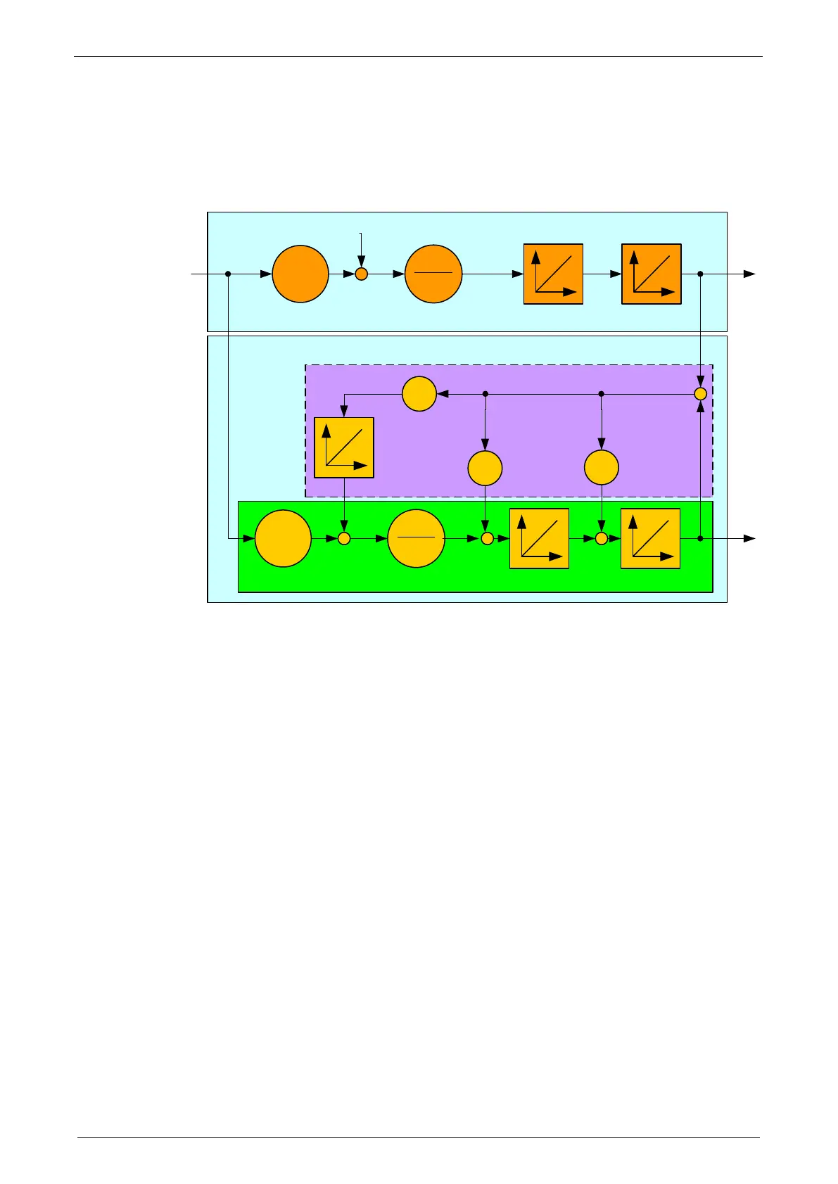
Signal flow chart Luenberg observer
-
Regelstrecke / controlled system
Beobachter / observer
I(t)
Nachführregler / tracking controller
Modell / model
I(t): Torque-forming motor current
Kt: Torque constant
ML(t): External disturbance torque
Jtotal: Total mass moment of inertia (motor + load)
a(t): Acceleration
n(t): Velocity
x(t): Position
Index b: Observed signal quantities
h0…h2: Controller coefficients of the tracking controller
The figure shows that an additional I element is connected for interference
compensation to correct external disturbance forces in the observer. Therefore the
speed and the acceleration observed are statically precise. The same applies to
the output of the integrator in the tracking controller which is a statically precise
determination of an external interference torque ML. For this reason, the I
component is not required in the speed controller for some applications, and the
entire control can be set up as a state cascade control. This increases the
bandwidth of the speed and position controlled member by factor 2. As a
consequence, the interference stiffness of the drive and the following error
behavior improve.
Here the quantization of the speed signal is proportional to the sampling time TAR,
hence there is no longer any conflict between the requirements for minimum
sampling time and minimum quantization noise. For the integral velocity
acquisition, the motor current variable, which is proportional to the acceleration,
can be used. This approach is particularly advantageous in direct drive
engineering; due to the absence of a mechanical drive train, there is a very good