EasyManuals Logo

Parker Compax3 User Manual

Parker Compax3
398 pages
To Next Page IconTo Next Page
To Previous Page IconTo Previous Page
Page #50 background imageLoading...
Page #50 background image
Compax3 device description
C3I12T11
48
192-120113 N08 C3I12T11 - December 2010
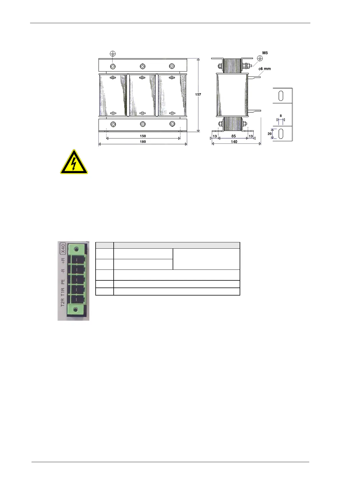
Dimensional drawing: LCG-0055-0.45 mH-UL
Caution - Risk of Electric Shock!
Always switch devices off before wiring them!
Dangerous voltages are still present until 10 min. after switching off the power
supply.
3.5.6. Braking resistor / temperature switch PSUP (mains module)
The energy generated during braking operation must be dissipated via a braking
resistor.
Connector X40
Pin
Description
+R + Braking resistor
short-circuit proof!
-R - Braking resistor
PE PE
T1R Temperature Switch
T2R Temperature Switch

Table of Contents

Other manuals for Parker Compax3

Questions and Answers:

Question and Answer IconNeed help?

Do you have a question about the Parker Compax3 and is the answer not in the manual?

Parker Compax3 Specifications

General IconGeneral
Protection ClassIP20
Control ModesTorque, Speed, Position
Feedback OptionsIncremental encoder, Absolute encoder, Resolver
Communication InterfacesCANopen, EtherCAT, Profinet
Safety FeaturesSTO (Safe Torque Off), SS1 (Safe Stop 1), SOS (Safe Operating Stop)
Input Voltage200-480 VAC
Relative Humidity5% to 85% (non-condensing)
Shock ResistanceAccording to EN 60068-2-27
Operating Temperature0°C to +40°C

Related product manuals