Parker EME
Setting up Compax3
192-120113 N08 C3I12T11 - December 2010
4.1.11. Encoder simulation
You can make use of a permanently integrated encoder simulation feature to make
the actual position value available to additional servo drives or other automation
components.
The encoder simulation is not possible at the same time as the encoder
input<ohne_SSI_t> resp. the step/direction input.
The same interface is used here.
A direction reversal configured in the C3 ServoManager does not affect the
encoder simulation.
The direction of rotation of the encoder simulation can, however, be changed via
the feedback direction in the MotorManager.
Simulated Encoder Output Resolution
Unit: Increments per
revolution / pitch
Range: 4 - 16384 Standard value: 1024
Any resolution can be set
Limit frequency: 620kHz (track A or B) i.e. , with:
Increments per revolution max. Velocity
1024 36000 rpm
4096 9000 rpm
16384 2250 rpm
4.1.11.1 Encoder bypass with Feedback module F12 (for
direct drives)
If the feedback module F12 is used, the encoder signals can be placed directly
(Bypass) to the encoder interface (X11: same assignment as encoder simulation)
for further use. Sine/Cosine signals are directly converted into encoder signals,
however no additional zero pulse is generated; an available zero pulse will be
transmitted.
The advantage is, that the limit frequency is 5MHz instead of 620kHz (track A or
B).
The direction of rotation is only defined via the encoder wiring; a direction inversion
configured in the C3 ServoManager does not have any consequence.
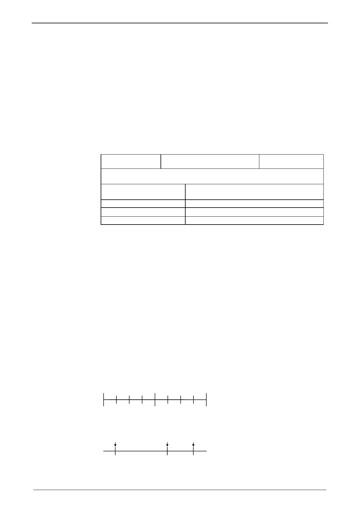
4.1.12. Absolute- /continuous mode
Operating mode: Absolute mode or continuous mode
A fixed measuring system is associated with the travel range: A fixed defined zero
point exists. All positions are referred to this zero point.
-100-200
-300
0
+100 +200 +300
The actual position is set to 0 before each positioning. Thus the travel range has no
fixed zero point. All positionings are relative - in relation to the actual position.