Setting up Compax3
C3I12T11
192-120113 N08 C3I12T11 - December 2010
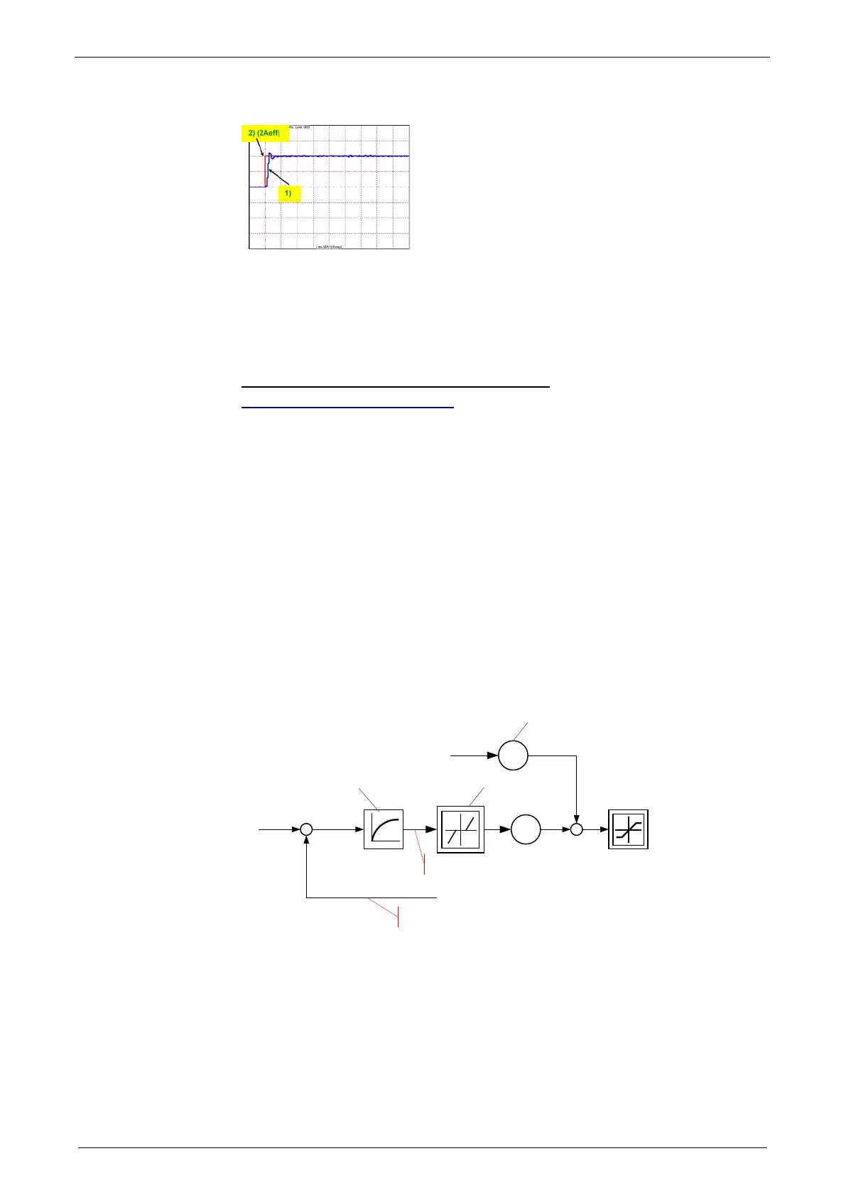
Current jerk response with the activated saturation characteristic line
The parameterization of the characteristic line is made in the MotorManager.
In order to accept the changes in the MotorManager in the project, the
entire configuration must be confirmed.
In order to make the changes from the MotorManager effective in the device, the
configuration download must be executed.
Control measures for drives involving friction
In this chapter you can read about:
Deadband following error ............................................................................................... 226
Friction compensation .................................................................................................... 227
Some drives, which involve much friction due to their guiding system, may show
permanent oscillation at standstill. The transition between static friction (standstill)
and kinetic friction (very low speed) is very steep. The controller can not longer
follow the friction characteristic line at this position. The I-term integrates until the
control variable pulls free the drive and the drive moves too far. This procedure is
repeated in the opposite direction and a control oscillation occurs (so-called limit
cycle). In order to eliminate this control oscillation, the following control functions
were implemented:
Deadband following error (Obj. 2200.20)
Filter following error (Obj. 2200.24)
Friction compensation (Obj. 2200.20)
Deadband following error
Deadband/filter following error in the position loop
-
T1
680.6 Position Tracking error
2010.1 Velocity feed-forward
2200.20 Deadband –
Tracking Error
2200.24 Filter - Tracking Error
680.5 Actual Position
The deadband does no longer supply a velocity setpoint value (zero) for the
subordinate velocity loop at small following error. The integrator of the velocity loop
stops integrating and the system comes to a standstill.
In order to prevent that the velocity loop is excited by the noise on the following
error, the following error should be filtered before the deadband, which will lead,
however, to delays in the position loop. The deadband to be set depends on the
friction behavior (amplitude of the limit cycle) and on the noise on the following
error (the noise must remain within the deadband).