Do you have a question about the Phoenix Contact AXC 1050 and is the answer not in the manual?
Specifies the intended application and operational environment for the controller.
Prohibits any alterations to the device's hardware or software.
Provides essential safety guidelines for installation, commissioning, and maintenance.
Details specific installation and operational requirements for Zone 2 explosive environments.
Provides instructions and precautions for transporting the device.
Specifies the environmental conditions required for storing the controller.
Outlines the procedure for inspecting the delivery for damage and completeness.
Details the process of unpacking the controller, including ESD precautions.
Lists the necessary hardware and software components for the controller.
Provides an overview of the controller's features and capabilities.
Explains various application scenarios and configurations for the controller.
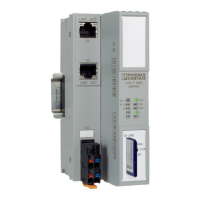
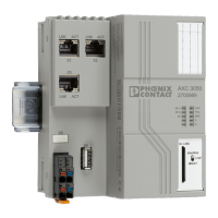
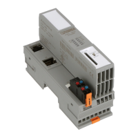
Identifies and describes the controller's physical connection interfaces and operating elements.
Explains the function of LEDs and other indicators for diagnostics.
Details the operation and modes of the controller's mode selector switch.
Describes the function and procedure for using the controller's reset button.
Explains the use of internal and external memory for project data.
Presents a schematic representation of the controller's internal circuitry.
Details the available communication interfaces and protocols.
Describes the connector for power supply and its terminal assignments.
Explains the function and structure of the bus base module for local bus connections.
Provides critical safety instructions related to mounting procedures.
Covers fundamental aspects of controller mounting and connections.
Illustrates the typical assembly of an Axioline F station.
Details the step-by-step procedure for mounting the controller onto a DIN rail.
Explains how to select and connect the appropriate power supply.
Describes how to establish Ethernet network connections.
Provides instructions for connecting the controller via USB.
Guides through the installation process of the PC Worx automation software.
Explains how to create a new project within the PC Worx software.
Details methods for setting the controller's IP address.
Describes how to read Axioline F module configurations into the project.
Explains how to configure and integrate PROFINET controller/device functions.
Provides instructions for configuring the controller's real-time clock.
Guides on compiling the project after setting up the bus topology.
Details how to use the SD card for main or additional memory functions.
Explains how to use the Diag+ 2 software for system diagnostics.
Describes how to enable immediate IP address application without a restart.
Covers file management via FTP and Internet Explorer.
Details how to activate/deactivate the web server (HTTP/HTTPS).
Explains how to configure secure email transmission using SMTPS.
Describes how to enable or disable specific communication ports.
Explains how to manage the file system journaling function.
Details how to control the Media Redundancy Protocol (MRP) client.
Guides on configuring event tasks for power failure scenarios.
Explains function blocks for managing files on memory devices.
Details function blocks for Ethernet TCP/IP and UDP/IP communication.
Describes function blocks for Axioline F communication.
Explains the function block for obtaining Coordinated Universal Time (UTC).
Describes the function block for retrieving communication partner information.
Discusses data alignment and padding bytes in memory for program creation.
Introduces system variables for diagnostics and control.
Details system variables for monitoring the Axioline F local bus state.
Explains system variables providing additional error information.
Lists PROFINET system variables for controller and device functions.
Describes system variables related to the IEC-61131 runtime environment.
Details system variables for monitoring the control processor's status.
Lists system variables for Ethernet interface link status.
Provides system variables related to SD card presence.
Describes system variables for energy storage and real-time clock status.
Lists system variables indicating the status of power supplies.
Details system variables reflecting the mode selector switch position.
Lists system variables related to project status and comparison.
Provides system variables for accessing the controller's system time.
Guides through the installation process for Web-based Management.
Explains how to connect to the controller's web interface.
Describes how to switch the WBM interface language between German and English.
Overviews the different sections within the Web-based Management interface.
Provides access to general device information and data.
Allows viewing diagnostic information for the controller and Axioline F devices.
Covers password management and firmware update information.
Provides a link to open the controller's WebVisit visualization project.
Provides essential safety guidelines for hardware removal.
Details the procedure for safely removing connecting cables.
Explains how to disconnect and remove the supply plug and connectors.
Describes the steps for safely removing the SD card.
Provides instructions for detaching the controller from the DIN rail.
States that the controller is maintenance-free.
Outlines the procedure for replacing the controller with an identical unit.
Explains the process for handling defective devices and repairs.
Provides guidelines for the proper disposal of the controller and packaging.
Summarizes key technical specifications and parameters of the controller.
Lists controller models, accessories, software, and documentation for ordering.
Provides instructions for updating the controller firmware via FTP or SD card.
Explains derating factors for the controller based on ambient temperature.
Presents successful test results under extreme ambient conditions.
| Brand | Phoenix Contact |
|---|---|
| Model | AXC 1050 |
| Category | Controller |
| Language | English |