AXC 1050 (XC)
36
PHOENIX CONTACT 8482_de_03
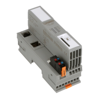
3.11 Supply plug
Figure 3-14 Terminal points for the supply voltage (communications power U
L
)
Terminal point assign-
ment
Key:
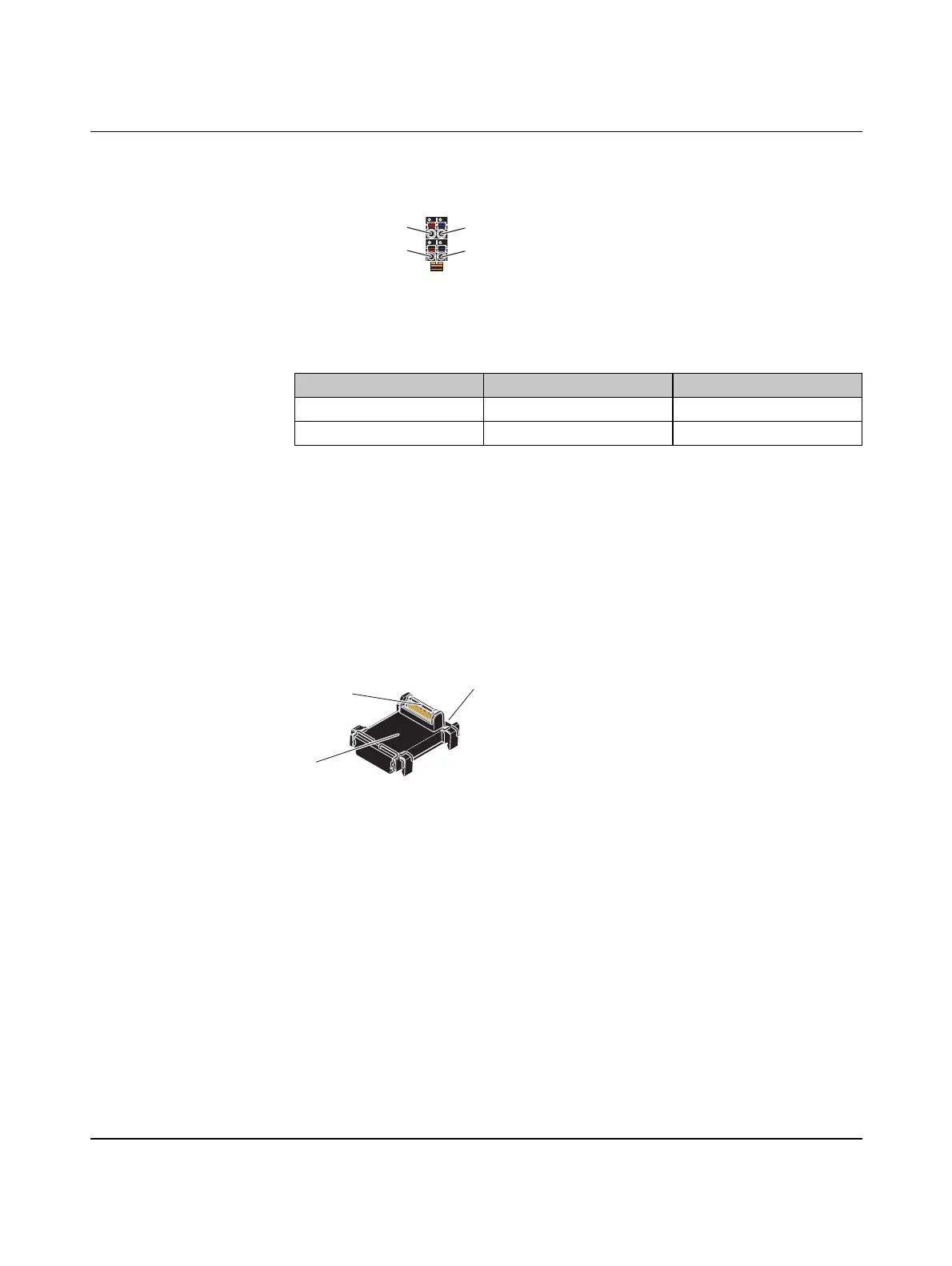
3.12 Bus base module
Bus base modules carry the communications power and the bus signals from the controller
through the Axioline F station (local bus). A bus base module is supplied with the controller.
Figure 3-15 Structure of the bus base module of the controller
1 Bus base module
2 Connection of the local bus to the controller (socket)
3 Connection to the following bus base module (socket)
a1
a2
b1
b2
a1
a2
b1
b2
Table 3-3 Terminal point assignment of the supply connector
Terminal point Color Assignment
a1, a2 Red 24 V DC (U
L
)
b1, b2 Blue GND
U
L
Communications power feed-in (internally jumpered)
GND Reference potential of the supply voltage (internally jumpered)
1
3
2
8482A010
 Loading...


