Connecting and wiring hardware
8482_en_03 PHOENIX CONTACT 43
5 Connecting and wiring hardware
5.1 Supply voltage
5.1.1 Sizing of the power supply
• Choose a power supply unit that is suitable for the currents in your application. The se-
lection depends on the bus configuration and the resulting maximum currents.
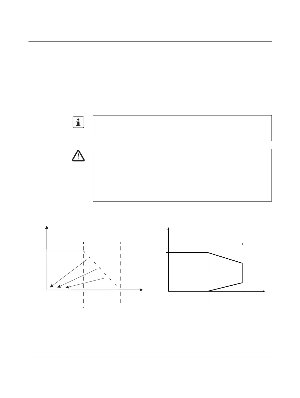
Some electronically controlled power supplies have a fall-back characteristic curve (see
Figure 5-1). They are not suitable for operation with capacitive loads.
A power supply without a fall-back characteristic curve must be used for correct op-
eration of the controller (see Figure 5-2).
When the controller is switched on, an increased inrush current is temporarily triggered.
The controller behaves like a capacitive load when it is switched on.
WARNING: Loss of electrical safety when using unsuitable power supplies
The controller is designed exclusively for protective extra-low voltage (PELV) operation
according to EN 60204-1. Only PELV according to the defined standard may be used for
supply purposes.
The following applies to the network (PROFINET) and the I/O devices used in it:
• Only use power supply units that meet EN 61204 with safe isolation and PELV ac-
cording to EN 50178 or EN 61010-2-201.
This prevents short circuits between primary and secondary sides.
Figure 5-1 Overload range with fall-back characteristic
curve
Figure 5-2 Overload range without fall-back charac-
teristic curve
24
U
OUT
[V]
I
OUT
[A]
6219B070
1.1 x I
N
2.4 x I
N
I
N
Overload range
with fall-back
characteristic curve
6219B071
24
U
OUT
[ ]
V
I
OUT
[ ]
A
I
N
1.5 x I
N
Overload range
without fall-back
characteristic curve
 Loading...


