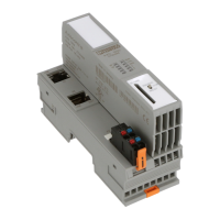
Description of the AXC 1050 (XC)
8482_de_03 PHOENIX CONTACT 17
Axioline F local bus There is an interface to the Axioline F local bus on the bottom of the controller. Bus base
modules are used to carry the communications power and the bus signals from the control-
ler through the Axioline F station. A bus base module is supplied with the controller.
Up to 63 Axioline F modules can be connected to the controller. The maximum number of
modules that can be operated depends on the current consumption of the modules. The
total current consumption of all devices aligned on the controller must not exceed the max-
imum current that the controller supplies for the local bus (2 A).
Axioline F/
System and firmware
For system-specific information on the Axioline F system, please refer to the online help for
the PC Worx software and the "Axioline F: System and installation"
(UM EN AXL F SYS INST) and "Axioline F: Diagnostic registers and error messages"
(UM EN AXL F SYS DIAG) user manuals.
MRP The MRP Media Redundancy Protocol protocol can be used via the Ethernet interfaces of
the controller. The controller supports the MRP client function, which can be enabled or dis-
abled via PC Worx. This function is disabled by default. If the function is enabled, it remains
enabled after the supply voltage is switched off and on. If the controller has been reset to
the delivery state, the MRP client function will also be disabled again. In a ring with Media
Redundancy Protocol, maximum switch-over times of up to 200 ms can be expected.
Service interface The service interface can be used to connect the controller to a PC running the
PC Worx (Express)/Diag+ or Startup+ software. The service interface is designed as a type
B Micro-USB socket.
The controller is detected as a USB device by the Windows
®
operating system if the corre-
sponding driver is installed on your PC (also refer to Section 6.1).
The following functions are available in the PC Worx (Express) software when using the ser-
vice interface:
– Setting/reading in the IP address of the controller
– Setting the real-time clock of the controller
– Enabling/disabling the SNMP agent
– Enabling/disabling the PROFINET controller/device function of the controller
– Resetting the controller (reset)
– Online diagnostics of the controller using the Diag+ diagnostics software
– Enabling/disabling the MRP client function
USB driver In order to use the service interface of the controller, the "Phoenix Contact USB to UART
Interface" driver must be installed. This must be selected explicitly when installing the
AUTOMATIONWORX Software Suite. See also Section 6.1.
NOTE: Electronics may be damaged if overloaded
The permissible number of devices that can be connected depends on the structure of the
Axioline F. The current consumption for each device is specified in every module-specific
data sheet and may vary. If the total current consumption for the connected devices ex-
ceeds the maximum current supplied by the controller, this can damage the electronics
due to overload.
• Observe the current consumption of each device when configuring an Axioline F sta-
tion.

 Loading...


