F5
JP1 JP2 JP4
GNDGND
OUT8 7 6 5 4 3 2 1 12V
J1
J2
JP3
Drawing 11-Connecting OUT-1000 to control panel
Use the cable to connect the control panel’s JP3 connector to OUT-1000’s JP1
connector.
NOTE:
OUT-1000 can be connected simultaneously with EXP-LOCAL by connecting
OUT-1000’s JP2 to EXP-LOCAL’s JP1 (see OUT-1000 Manual for instructions).
Configure the outputs’ polarity
Configure which partition activates which output in “Output Configuration”
screen (see section 5.8).
3.10
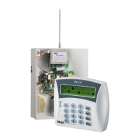
Connecting Keypads
Connect the keypad’s “+” “-“ “IN” “OUT” outputs to the compatible ones on
control panel.
NOTE:
Up to 8 keypads can be connected to the system.
IMPORATNT!
The 4 wires used to connect the keypad must be totally separate.
The keypad’s power source (-) / (+) cannot be used for detectors.

 Loading...