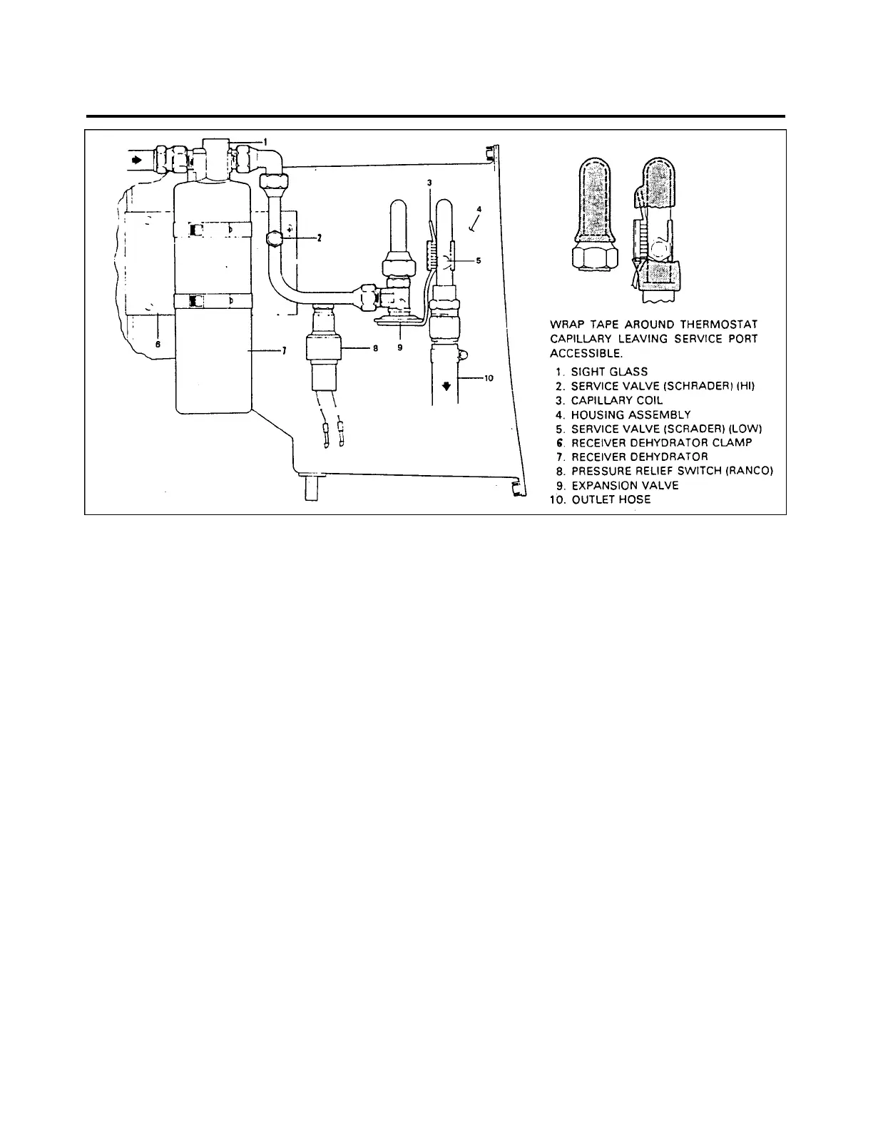
Figure 21-15. Components Installation
PRESSURE RELIEF SWITCH (Ranco)
The pressure relief switch automatically prevents system over pressurization by breaking electrical circuit
to magnetic clutch. This stops the compressor until pressure is reduced. The switch is located in line between
receiver and expansion valve.
—NOTE—
Before relief switch is removed, air conditioning system must be
discharged (See Discharging.)
ELECTRICAL INSTALLATION
The wiring harness is connected to the climate control switches on right side of instrument panel. The
harnesses cross instrument panel to left side where two wires are taken off compressor clutch. The harness then
passes aft along left side of fuselage where it connects to blower motor, pressure relief switch, and condenser
actuating motor.
21 - 59 - 00
Page - 21 - 37
Reissued: August 1, 1986
1H3
PIPER AIRCRAFT
PA-28-236
MAINTENANCE MANUAL