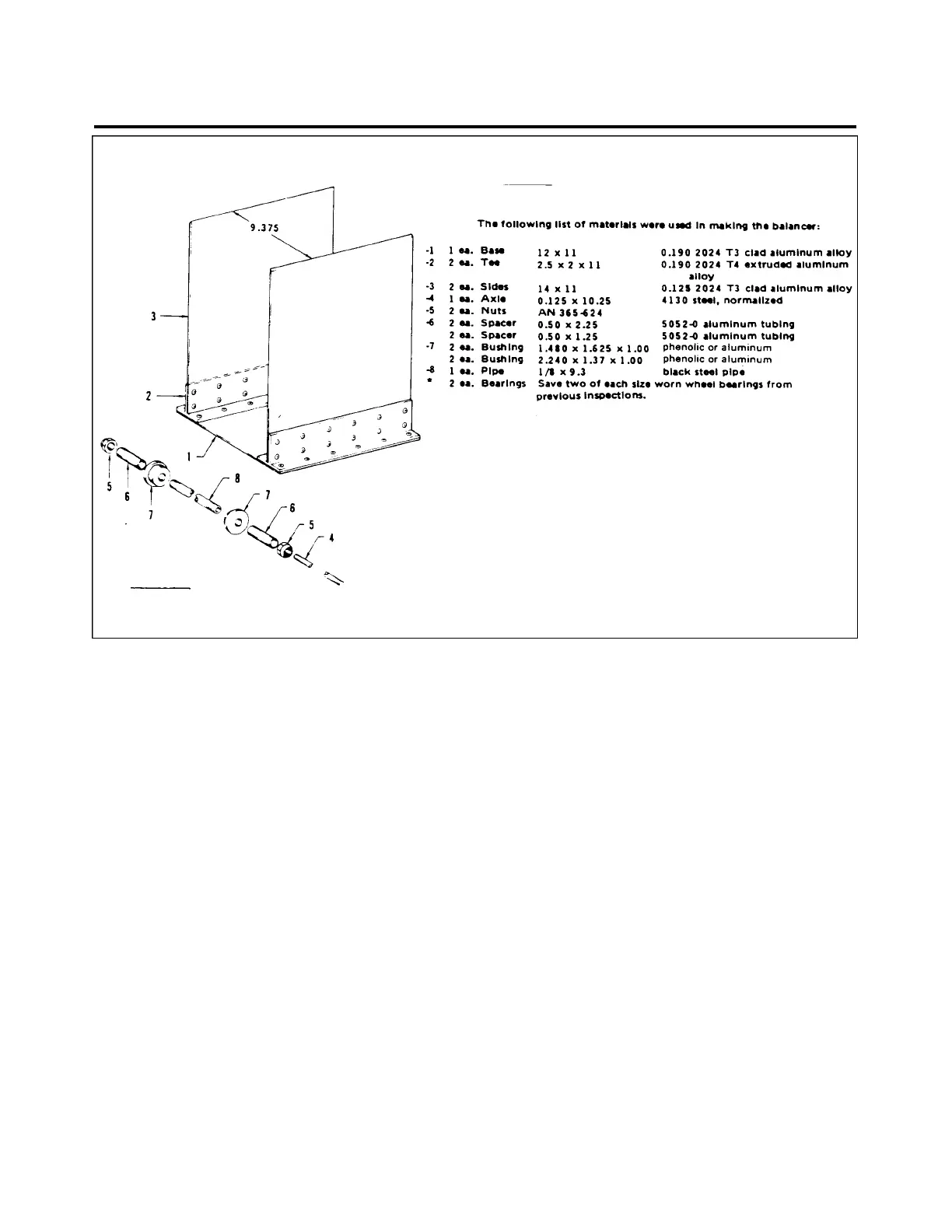
Figure 95-1. Tire Balancer Fixture
TIRE BALANCER BUILDING INSTRUCTIONS
1. Chamfer top edges of -3 sides, heaving 1/16 inch flat on top inboard edge. Rivet -2 tee’s to -3 sides
using AN470-AD5 rivets 2” spacing. Use AN426-AD5 rivets 2” center to center to secure -2 tee’s to -
1 base. If tee extrusion is unavailable, heavy angle extrusion may be used, -3 sides must be vertical.
2. The 4 axle must slide through -8 pipe. The -5 nuts are made by reaming existing threads in AN365-
624 nuts with an R drill, then tapping with a 1/8-27 pipe tap.
3. The -6 spacers are made from 1/2 inch aluminum tubing. The two lengths of spacers are suitable for
balancing any aircraft wheel.
4. The -7 bushings are made from one inch phenolic or aluminum with a 1-1/2 hole saw to cut out
smaller bushing and a 1-3/4 hole saw to cut out larg e r. By inserting a 1/4 inch long threaded bolt
through pilot hole and securing with a washer and nut, a drill press and file are used to make off-set on
bushing. The turned-down part should just side inside bearing race. Ream pilot hole to side over-8 pipe
threads.
5. The -8 pipe is made from a piece of 1/8 inch black pipe and threaded with a 1/8-27 pipe die. Thread 3
inches from each end of pipe.
-
95 - 10 - 00
Page 95 - 02
Reissued: August 1, 1986
3D4
PIPER AIRCRAFT
PA-28-236
MAINTENANCE MANUAL