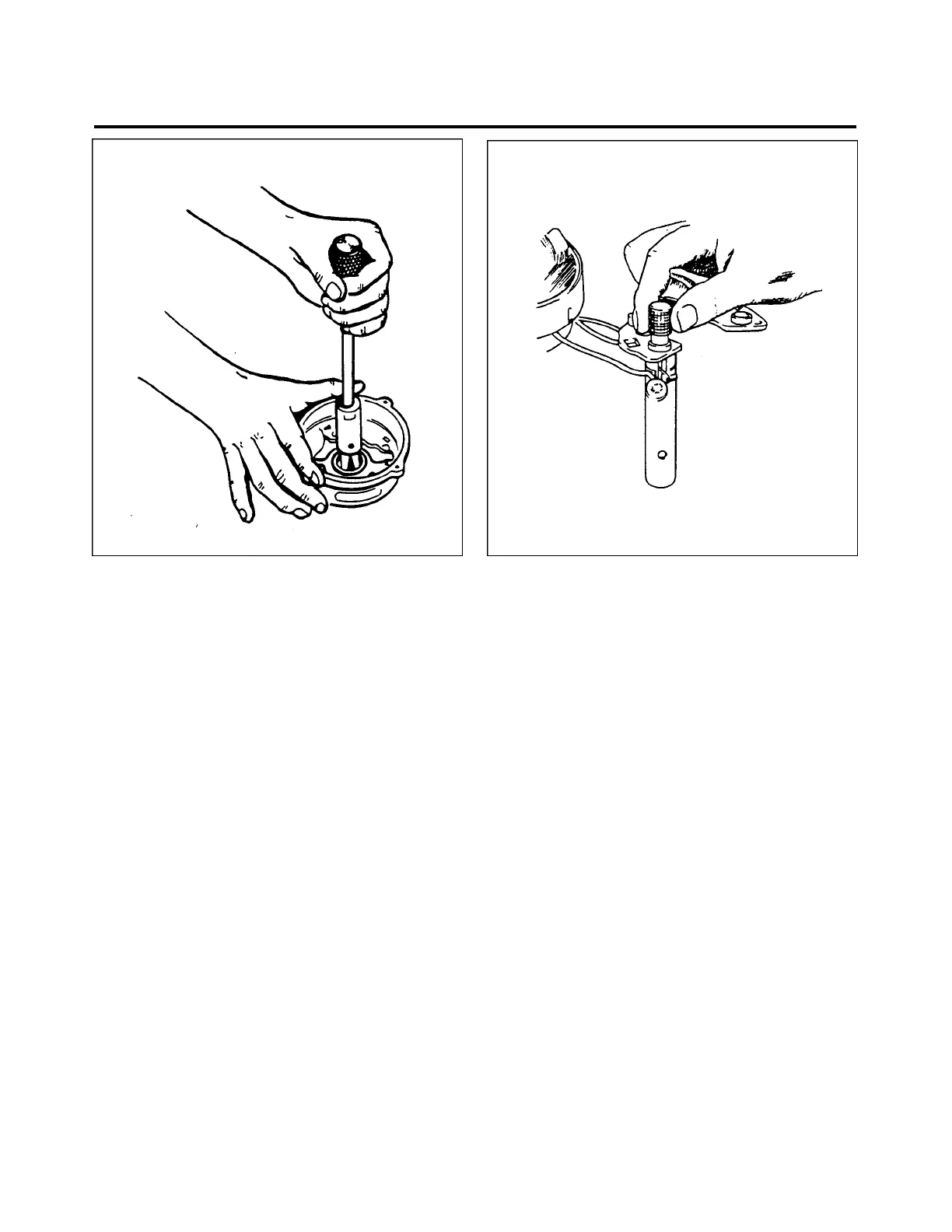
Figure 24-38. Slip Ring End Bearing Assembly Figure 24-39. Testing Alternator
6. Assemble alternator and install through bolts. Spin rotor to make sure there is no mechanical
interference. Tighten bolts to a torque of 30 to 35 inch-pounds. Install safety wire after unit has been
bench tested for output. Install spacer, woodruff key, fan, pulley, lockwasher, and nut. Tighten nut to a
torque of 35 foot-pounds, using a strap wrench to hold pulley.
7. Install brush holder assembly and retaining screws. Spin rotor and check for interference between
brush holder and rotor. Check between field terminal and ground with ohmmeter. Ohmmeter must
indicate amount of rotor resistance listed. (Refer to chart 2403, Alternator Specifications.)
TESTING ALTERNATOR
1. Wiring connections for bench testing alternator are shown in figure 24-39. Refer to individual
specification chart 2403 for output test figures. Adjust carbon pile if necessary, to obtain specified
voltage.
2. After bench testing alternator, install safety wire and install alternator on engine.
—NOTE—
Always refer to wiring diagram (refer to figure 24-39) when
installing or testing alternator.
24 - 33 - 00
Page - 24 - 33
Reissued: August 1, 1986
1J8
PIPER AIRCRAFT
PA-28-236
MAINTENANCE MANUAL