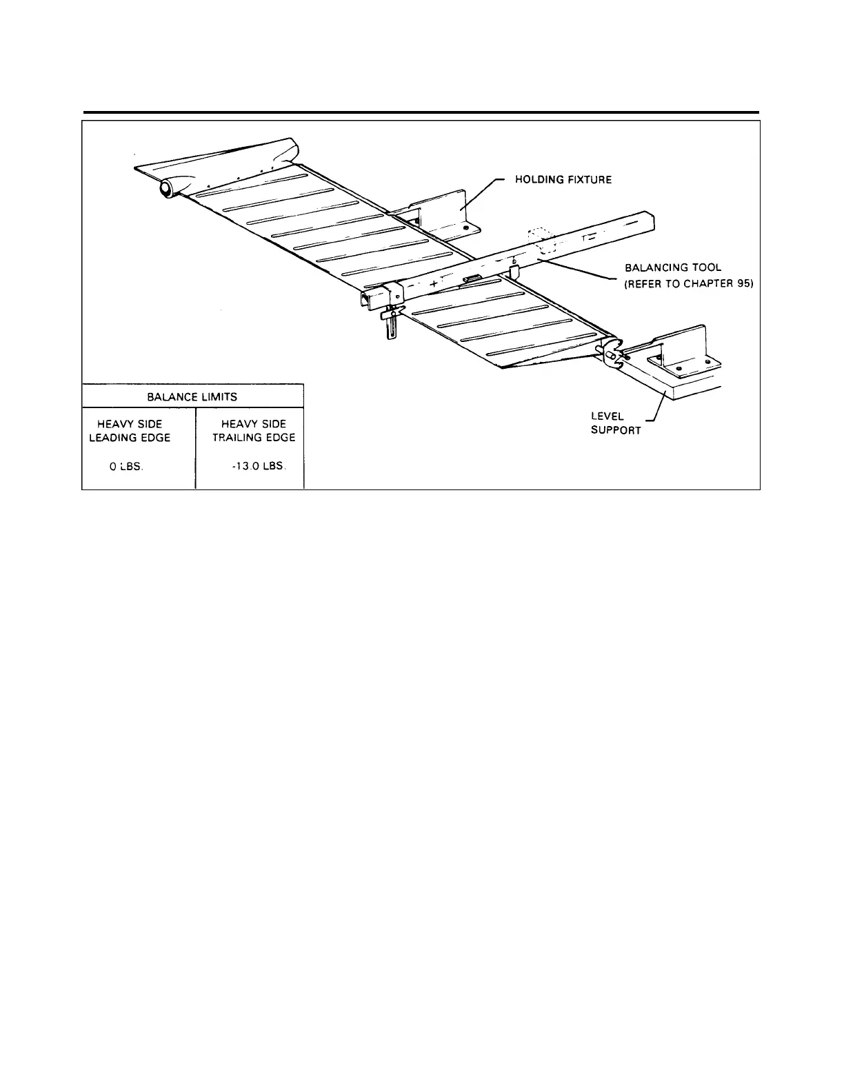
Figure 55-4. Rudder Balance
2. Connect tail position light electrical lead at quick disconnect and cover connector with an insulating
sleeve. Tie both ends of sleeve with number six electrical lacing twine.
3. Connect control cables to rudder horn with bolts, washers, nuts, and cotter pins.
4. Check rudder in accordance with Rigging and Adjustment of Rudder, chapter 27.
5. Install upper tail cone fairing and rudder tip and secure with attachment screws. Secure access panel to
aft section of fuselage.
BALANCING
BALANCING RUDDER (figure 55-4) PPS50015
To balance the rudder, the assembly must be complete including the tip assembly with all attaching screws
and the position light wiring. Place the complete assembly horizontally on knife edge supports in a draft free
area that allows unrestricted movement.
1. Place the tool on rudder with the beam perpendicular to hinge centerline.
2. Calibrate tool as described in chapter 95. Read scale when bubble level has been centered by
adjustment of movable weight and determine the static balance limit.
3. If the static balance is not within the limits given in figure 55-4, proceed as follows:
55 - 42 - 00
Page - 55-07
Reissued: August 1, 1986
2G5
PIPER AIRCRAFT
PA-28-236
MAINTENANCE MANUAL