GENERAL
This chapter contains information necessary to perform operational checks of the emergency locator
transmitter (elt). Included are appropriate removal and installation instructions to facilitate battery replacement.
AVIONICS MASTER AND EMERGENCY SWITCH CIRCUIT (figure 23-1)
DESCRIPTION AND OPERATION
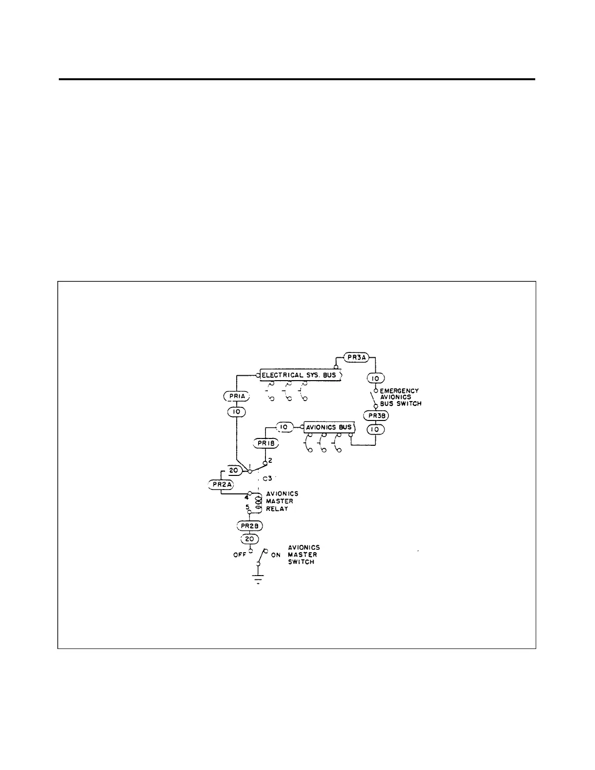
Electrical power for various avionics components is controlled by an avionics master switch located near
the top of the instrument panel between radio stacks. It controls power to all radios through the aircraft master
switch.
An emergency bus switch is provided to supply auxiliary power to avionics bus in event of a radio master
switch circuit failure. The emergency bus switch is located behind lower right shin guard, to left of the circuit
breaker panel.
Figure 23-1. Avionics Master and Emergency Switch Circuit
23 - 11 - 00
Page - 23 - 02
Reissued: August 1, 1986
1H14
PIPER AIRCRAFT
PA-28-236
MAINTENANCE MANUAL