PAGE 2
Nov 30/06 4D12
51-80-00
PIPER AIRCRAFT, INC.
PA-28-161, WARRIOR III
MAINTENANCE MANUAL
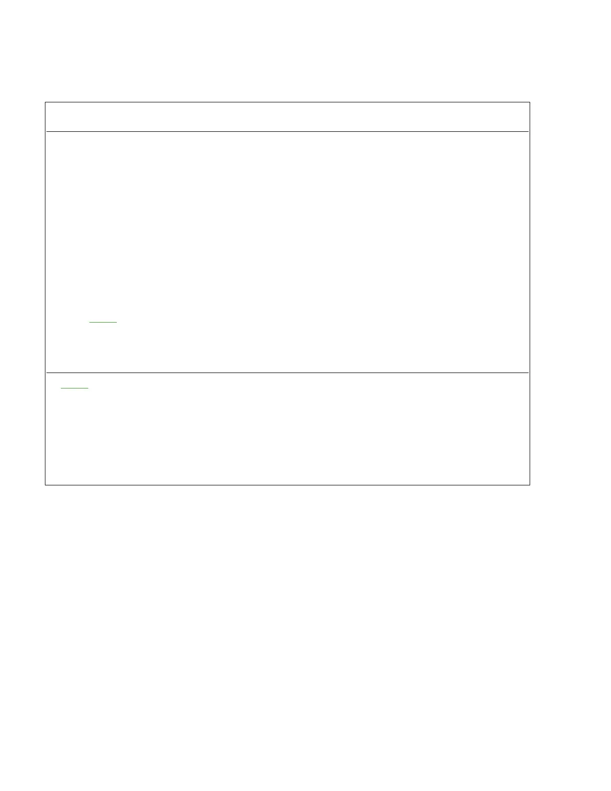
CHART 1
ELECTRICAL BONDING RESISTANCE INDEX
Maximum Allowable
Component Resistance Value in Ohms
Engine Mount(s) .003
Generator(s) .010
Ailerons .003
Elevator / Stabilator .003
Rudder .003
Alternator(s) .010
Trim Tab(s)
Conventional Hinge .003
Piano Hinge .010
Instrument Panel Inserts .010
Exterior Lights Mounted on Non-Conductive Material .003
Avionics ‘Black Boxes’ .003
NOTE: Harnesses should be installed and connected for this check, internal chassis
wiring through the connector to ground is permissible for this grounding.
Battery Ground Point .010
Static wick mounting plates (TCO Model B-4) P/N 452-094 1.00
NOTE
: Where jumper wires or cables are used to accomplish a proper bond, resistance between
the jumper terminal and the component or structure shall not exceed .001 ohms. The
controlling points for measuring resistance will be within the limits of the cleaned area to be
bonded and within 1/4 inch of the exterior limits of the bonding jumper terminal or material
called for in the bill of materials of the drawing.
Resistance to ground will be measured from wire terminal to structure for electrical /
electronic equipment not internally grounded and from mounting flange to structure for
equipment that is internally grounded.