Appendix III, continued
99
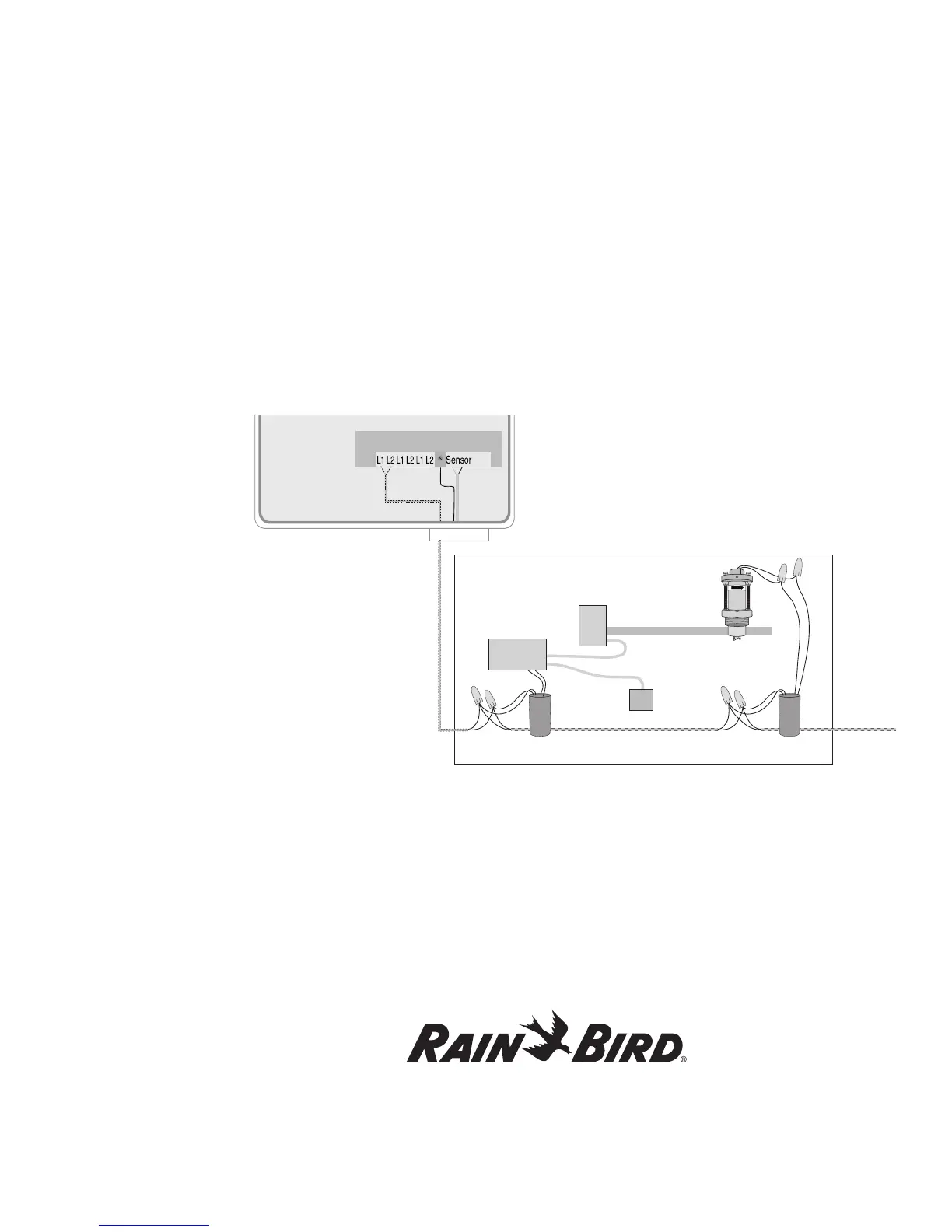
Using a Decoder and Relay-100 With a Pressure Switch
In this installation, the pressure switch attaches directly to the decoder and Relay-100, and the decoder
and Relay-100 to the pump. Please see the illustration below.
Please see Naming the Field Decoders on page 25. You will also need to define a separate valve type with
the switch code of 4FFA20. The controller circuit from the pressure switch runs through the contacts on
the Relay-100.
With the above setup, the pressure switch will provide power to the pump, or if the flow exceeds the maximum
rate, the controller sends a signal to the field decoder stopping the pump and shutting off the valves in the system.
If the pressure is too high, the pressure switch will cut off power to the pump and shut it off. With the valves
closed, any flow in the system is considered a leak.