Programming and Operation, continued
28
Note: Rain Bird
®
decoders that have more than
one output, (FD-202TURF, FD-401TURF and
FD-601TURF) are considered multiple decoders.
You must list the separate Address (REC. NO.)
for each solenoid/master valve connection (i.e.,
brown 40216, red 40217, etc.) Treat each Address
(REC. NO.) as a separate decoder and give each a
separate name.
15. Once you identify each decoder in your
irrigation system, move the markers to Finish
and select OK to return to the Set-up Data
menu.
Decoders Failed
This is a list of valve decoders that have failed due to
triggering SEUF (Seek and Eliminated Unexpected
Flow) and have been blacklisted. A decoder on the
list will not be activated during irrigation.
1. From the Main Menu, select 1. Setup Data and
then select OK. The Setup Data Menu appears.
2. Select 3. Decoders Failed to conduct an audit of
your valves.
Any valve decoders that have caused SEUF and are
blacklisted shall be listed on the display window.
If any of them have been found to be working
properly or have been fixed, the user must take
them off of the black list for the valves to run again.
Entering the Pump/Master Valve
Information
The MDC2 Controller supports master valves,
master pumps and up to nine booster valves
or pumps. Rain Bird
®
recommends you use one
Relay-100 pump start relay for each pump in your
system. However, in place of a pump start relay,
your irrigation system may start pumps using a field
decoder plus an external pressure switch, or use a
master valve with a field decoder. For the controller
to recognize and associate a field decoder to the
master valve and pumps your system uses, you
must program in the decoder’s Address and verify
or change the switch code.
1. From the Main Menu, move the indicating
arrow to 1. Set-up Data and select OK.
2. Move the indicating arrow to 4. Pumps/Master
Valves and select OK to reach the Pumps
screen. It lists one Master pump or valve and
nine Booster pumps and their switch codes.
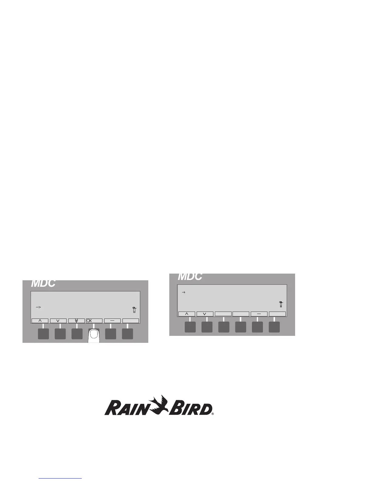
3. Move the indicating arrow to 1. Master, and
select OK. The screen now shows 3 fields with
the titles: Pump; Switch; Address and On and
Off. A pair of markers points to the Switch field.