B-SERIES INSTALLATION, OPERATION AND SERVICE MANUAL
62 of 147
Step 12.3.12
For inlet hoods with permanent aluminum mesh filters, the instructions end here.
Step 12.3.13
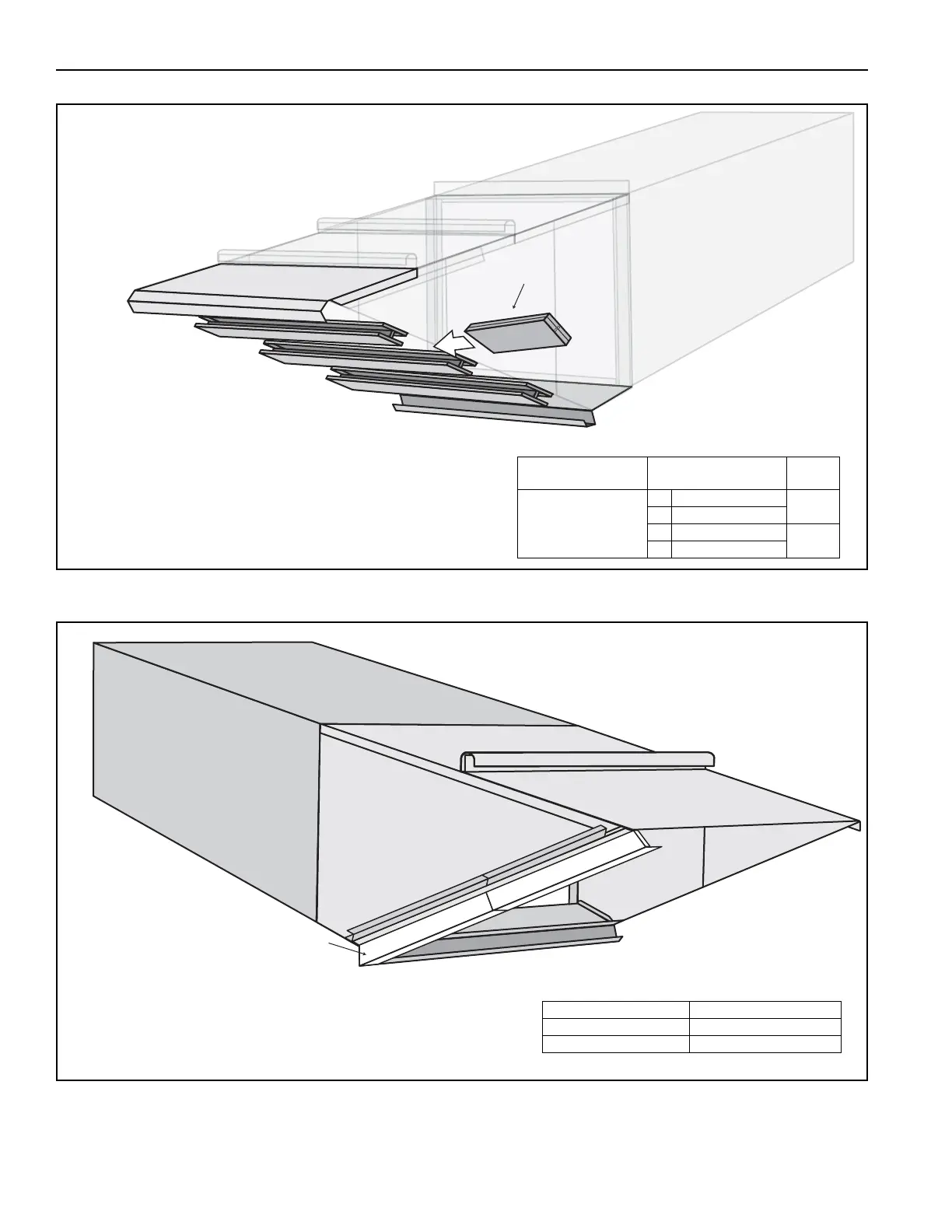
Load filters into the inlet hood, checking
to see that each filter is in the proper orientation
by verifying that the arrow on the side of the filter points in
the direction of air flow. All of the arrows should be
pointing towards the air handler when installed in the
proper orientation. Once filters are installed, close snap
fasteners installed previously (See Page 60, Step 12.3.9)
to hold filters in place.
Description Size
Part
Number
Permanent Aluminum
Mesh Filter
in 20 x 25 x 1
20629
cm 50.8 x 63.5 x 2.5
in 20 x 20 x 1
20628
cm 50.8 x 50.8 x 2.5
Moisture Limiter Side Cover
Attach side cover of moisture limiter frame to the left side
of the inlet hood drip rail using eight TEK screws. Attach
to the bottom pan assembly with two #10-24 x ½" bolts
and #10-24 nuts.
Description Part Number
Left Side Cover (ML) 13205078 / 13305078
TEK Screw 13404