103
8. Use a T5 Torx screwdriver to remove the four M1.6 x 0.35mm screws from the back of
the Hadron camera. Set the screws aside for re-use.
9. Pull the Hadron camera away from the gimbal.
10. Check the gasket around the PCB on the Hadron camera is properly aligned. Adjust if
needed.
11. Push the Hadron camera onto the gimbal. Press straight down until you feel the
connector click into place.
12. Use a T5 Torx screwdriver to secure the four M1.6 x 0.35 mm screws in the back of the
Hadron camera.
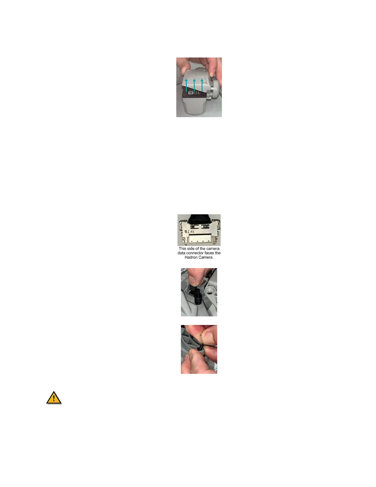
13. Connect the camera data cable connector to the mating socket in the AV. The side of
the cable is facing toward the front of the AV.
14. Connect the gimbal motor cable connector to the mating socket in the AV. The tab on
the connector faces the front of the AV.
15. Align the rubber grommets on the gimbal under the holes on the gimbal brackets.
16. Pinch and pull the rubber grommets through the bracket holes.
The exposed PCB is ESD sensitive and static discharge can damage the
electronics. Minimize handling of the exposed PCB.
 Loading...