Because RFL™ and Hubbell® have a policy of continuous product improvement, we reserve the right to change designs and specifications without notice.
IMUX 2000E1 RFL Electronics Inc.
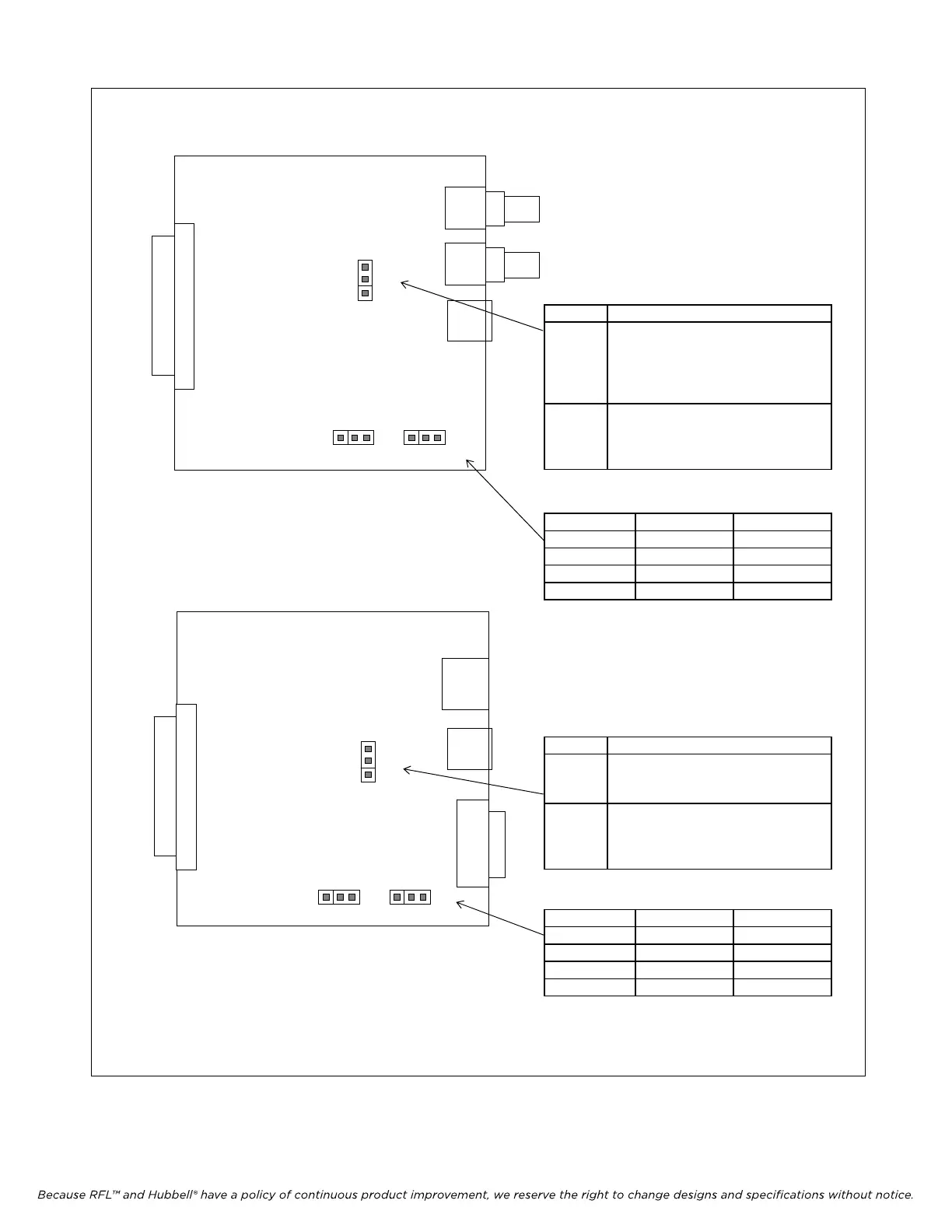
J3 Application
U Place jumper in U position to
unground the outer conductor of
the Receive Port “RX IN”. This is
the normal position for this
jumper.
G Place jumper in G position if
outer conductor of customers
equipment “TX OUT” is not
grounded.
J2 Mode 0 J1 Mode 1 CM4 Mode
0 0 TERM
1 0 D/I-A
0 1 D/I-B
1 1 SPARE
J5 Application
E1 Place jumper in E1 position for
normal E1 system operation.
Does not provide a current loop.
CSU Place jumper in CSU position to
provide a “loop current” path
through the transformer for CSU
in T1 systems only.
J2 Mode 0 J1 Mode 1 CM4 Mode
0 0 TERM
1 0 D/I-A
0 1 D/I-B
1 1 SPARE
RX IN
U
J3
G
MA-271
Figure 5-1. Location and use of setup jumpers on the MA-271 and MA-278 Module Adapters.
See Figure 2-12 for front panel view
J2 J1
1 0 1 0
MODE 0 MODE 1
E1
J5
CSU
MA-278
See Figure 2-13 for front panel view
J2 J1
1 0 1 0
MODE 0 MODE 1
January 1, 2008 5-2 (973) 334-3100


 To Next Page