Because RFL™ and Hubbell® have a policy of continuous product improvement, we reserve the right to change designs and specifications without notice.
J4 Application
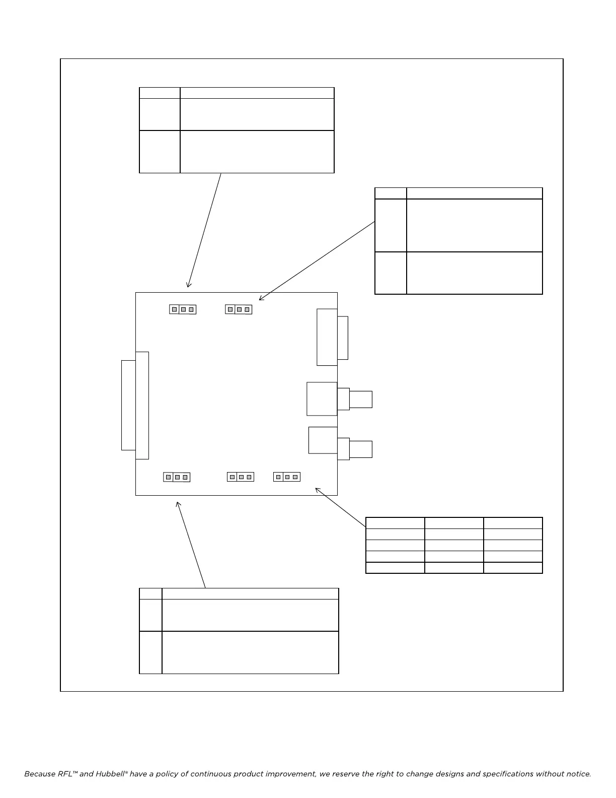
E1 Place jumper in E1 position for
normal E1 system operation. Does
not provide a current loop.
CSU Place jumper in CSU position to
provide a “loop current” path
through the transformer for CSU in
T1 systems only.
IMUX 2000E1 RFL Electronics Inc.
J9 Application
U Place jumper in U position to
unground the outer conductor
of the Receive Port “RX IN”.
This is the normal position for
this jumper.
G Place jumper in G position if
outer conductor of customers
equipment “TX OUT” is not
grounded.
J2 Mode 0 J1 Mode 1 CM4 Mode
0 0 TERM
1 0 D/I-A
0 1 D/I-B
1 1 SPARE
J8 Application
U Place jumper in U “ungrounded” position
if RJ48C or DB15 are being used. This is
“symmetrical pair mode”.
G Place jumper in G “grounded” position if
BNCs are being used (TX OUT/RX IN).
This is “coaxial pair mode”. Applies to E1
only.
Figure 5-2. Location and use of setup jumpers on the MA-270R Module Adapter.
MA-270R
J8 J2 J1
U G 1 0 1 0
TX OUT MODE 0 MODE 1
CSU
E1
J4
J9
G U
RX IN
See Figure 2-14 for
front panel view
January 1, 2008 5-3 (973) 334-3100
 Loading...
