Because RFL™ and Hubbell® have a policy of continuous product improvement, we reserve the right to change designs and specifications without notice.
c. Repeat steps 1a and 1b to verify that the CM4 is now in the terminal mode.
2. Change Transmitter Timing to INT (internal).
a. Press down on the Group switch several times to display the TIME group.
b. Press down on the SET/NEXT switch several times to display the INT function.
c. Press up on the SET/NEXT switch twice to set timing to internal.
3. Verify that E1 line code and frame format are setup as required (TSEL Group).
4. Use one of the following methods to establish a local E1 loopback:
a. Use a Bantam-Bantam patch cord to connect the E1 EQUIP OUT jack to the E1 EQUIP
IN jack.
b. If the multiplexer has an electrical E1 interface, connect an external looping plug to the
15-pin D-subminiature E1 connector (DA-15) on the MA-270R Module Adapter.
c. If the multiplexer has a fiber optic interface, connect a fiber optic patch cord between
the fiber optic connectors on the Optical Interface Adapter (OIA).
d. Use the Group switch to display the LPBK group and then the SET/NEXT switch to set
(activate) the EqLB (equipment loopback).
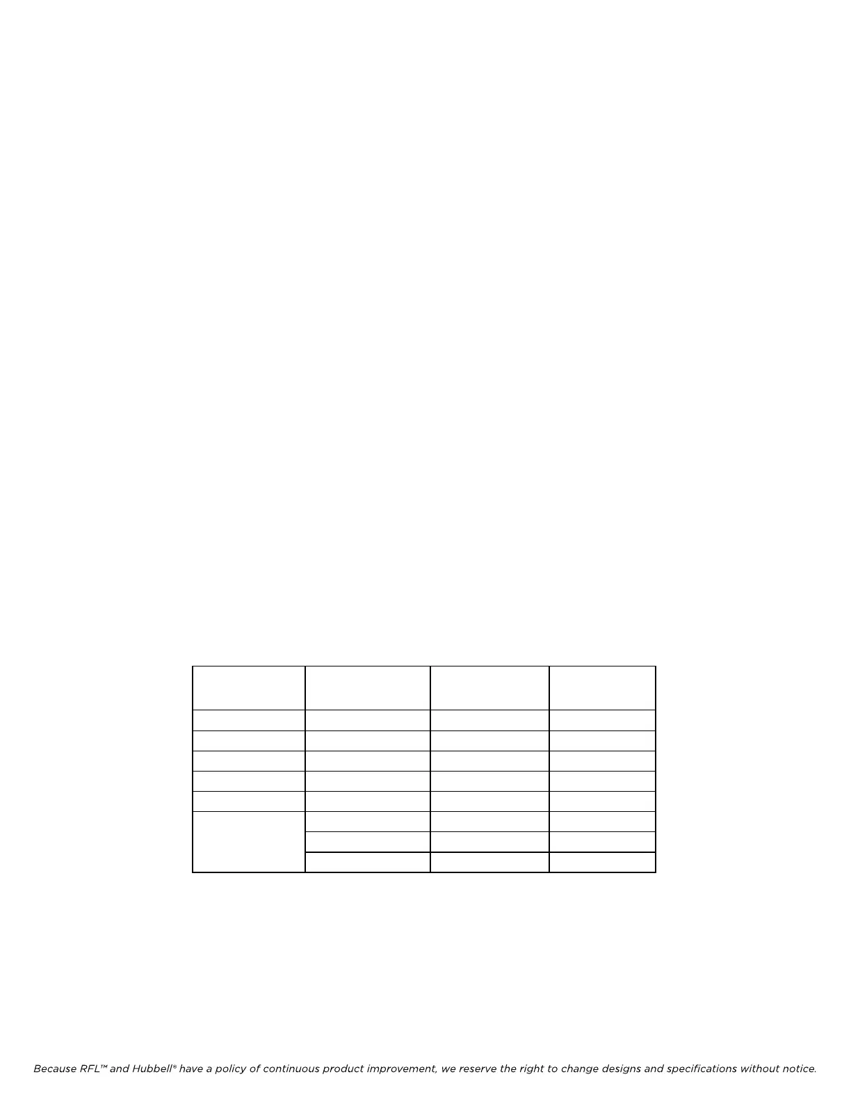
5. Once the loopback is established, verify the states of the indicators shown in Table 8-4.
Table 8-4. Indicator status during terminal multiplexer loopback (loop timing)
Module LED Indicator Patch Cord
Loopback
(1)
EqLB
Loopback
CM4 RX ON
ON
ERR and BPV OFF OFF
FRM OFF OFF
INT ON ON
LPBK OFF ON
Power supply NORMAL ON OFF
ALERT OFF ON
ALARM OFF OFF
1. Electrical or fiber optic.
IMUX 2000E1 RFL Electronics Inc.
January 23, 2004 8-20 (973) 334-3100