Because RFL™ and Hubbell® have a policy of continuous product improvement, we reserve the right to change designs and specifications without notice.
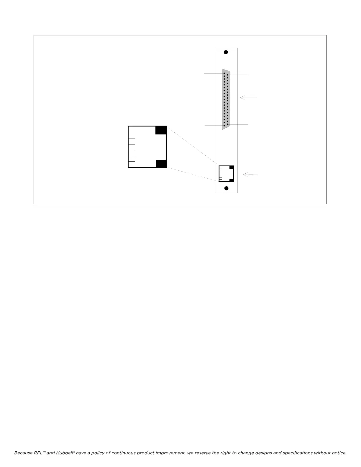
MA41x
6
5
4
3
2
1
PIN 37
RS449
or
V.35
CLK
OUT
PIN 19
PIN 20
PIN 1
DB-37S
RJ-11
Not Used
Not Used
Ground
Ground
Reference Timing Out
Reference Timing Out
Figure 1. MA-412A, MA-413A, MA-414A and MA-415A Module Adapters
Each Module Adapter has an RJ-11 jack for timing output and a 37-pin
D-subminiature connector for data signals (a DB-37S female connector). The
timing output may be applied to the timing input on the multiplexer’s Common
Module to synchronize the system timing to the RFL DS-64NC’s receive clock
signal.
4. If you are using an MA-412A Module Adapter, check the settings of all jumpers on the jumper
block near the motherboard mating connector. (See Figure 2 for location.) If you are using an
MA-413A Module Adapter, check the settings of all jumpers on the jumper block near the
center of the board. (See Figure 3 for location.)
The jumpers on MA-412A and MA-413A Module Adapters determine the
derivation of the transmit clock signal for the RFL DS-64NC module. Three
settings are possible:
NORMAL Transmit clock is sent from the Module Adapter to the
DTE, and the data is clocked in on the falling edge of
the clock signal.
INVERTED Transmit clock is sent from the Module Adapter to the
DTE, but the data is clocked in on the rising edge of
the clock signal instead of the falling edge.
EXTERNAL Transmit clock is derived from the DTE (the SCTE
signal).
5. If you are using the MA-427 Module Adapter, refer to page 47 for installation instructions.
RFL DS-64NC RFL Electronics Inc.
August 1, 2007 5 (973)
334-3100


 To Next Page