Because RFL™ and Hubbell® have a policy of continuous product improvement, we reserve the right to change designs and specifications without notice.
RFL DS-64NC RFL Electronics Inc.
August 1, 2007 50 (973)
334-3100
Verifying LAN-to-LAN Operation
Once you have completed the installation, verify that the MA-427 LAN Bridge is operating properly
by checking LAN-to-LAN operation with your network administrator. You can also verify the
operation of the MA-427 by checking its LEDs. Table 15 describes the LEDs and their state under
normal operating conditions when connected to a functioning LAN.
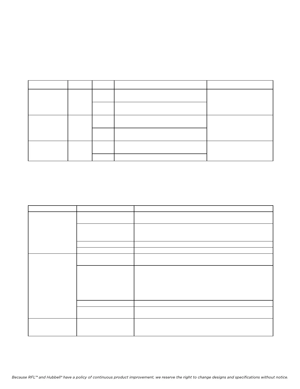
Table 15. MA-427 LAN Bridge LEDs
LED Color State Function Normal State
WAN TX/RX Yellow On Indicates transmission of data to or
receiving data from the WAN
This LED will flash on and
off when connected to a
Off Indicates transmission of data to or
receiving data from the WAN
functioning WAN
LAN TX/RX Yellow On Indicates no transmission of data to or
receiving data from the LAN
This LED will flash on and
off when connected to a
Off Indicates transmission of data to or
receiving data from the LAN
functioning LAN
LINK Green On Indicates connection to LAN This LED should always be
on when connected to a
Off
Indicates no connection to LAN functioning LAN
Troubleshooting
Use the table below to troubleshoot any problems you encounter during installation or operation of the
MA-427 LAN Bridge.
Table 16. Troubleshooting Problems and Solutions for the MA-427 LAN Bridge
Problem Probable Cause Solution
LINK LED is not on No LAN connection Remove and reconnect the RJ-45 cable connected to the MA-427
port.
Wrong cable for device
connection
Check that the proper cable is being used. Use UTP RJ-45 for hub
or Ethernet switch. Use UTP RJ-45 with crossover for PC or NIC.
See Table 14 on page 49.
Problem with LAN See your network administrator
T1/E1 link is not working Contact your T1/E1 service provider
No LAN-to-LAN
communication (data
No LAN connection Verify that the LINK LED is on. If it is not, see “LINK LED is not
on” above
is not being sent or
received)
Incompatible switch
settings
Verify that the COMPR switch settings are the same at both ends of
the network.
Verify that the FILTER switch settings are the same on both ends
of t
he network.
Verify that the WMODE and MODE 0-4 switches are set to their
defaults
. See Table 13 on page 48.
Problem with LAN See your network administrator
Synchronous data link is
not working
Check the operation of the DS-64NC using the DS-64NC
troubleshooting procedure on page 37
WAN TX/RX LED
and LAN TX/RX
LED are always on
MODE 0 switch is in the
DOWN posit
ion
Set the MODE 0 switch to the UP position. See Figure 11 on page
48 for the switch location.