Because RFL™ and Hubbell® have a policy of continuous product improvement, we reserve the right to change designs and specifications without notice.
FUNCTIONAL DESCRIPTION
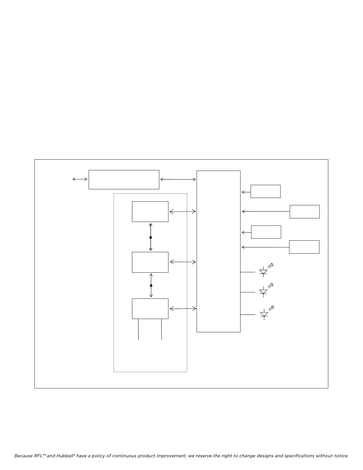
Figure 6 is a simplified block diagram of the RFL VF-10D module. The module consists of one audio
circuit which uses the digital interface and control logic circuitry. The audio circuit contains a Data
Access Arrangement (DAA) hybrid circuit which serves as the interface to the telephone line. The
hybrid contains circuitry for combining the transmit and receive audio, controlling loop current, and
ring voltage detection. The hybrid also provides the required isolation of the external signals.
The audio signals (both transmit and receive) are processed by a volume control circuit to adjust
levels. The analog-to-digital (A/D) and digital-to-analog (D/A) conversions and companding are
performed by CODECs.
The interface to the multiplexer backplane is performed by bus drivers and receivers. All of the
controlling logic functions are contained in the logic array. This custom device reads the local
switches, controls the LEDs and audio circuits, and interfaces to the bus and common logic module.
LOGIC
ARRAY
BUS DRIVERS
AND RECEIVERS
DIP SWITCH
SW1
TO/FROM
IMUX 2000
DATA BUS
CH1 RING
CH1 BUSY
SERVICE
DIP SWITCH
SW2
DIP SWITCH
SW9
DIP SWITCH
SW10
PCM
CODEC
DATA
ACCESS
ARRANGEMENT
TIP RING
TX AND RX
TEST POINTS
VOLUME
CONTROL
TX AND RX
TEST POINTS
CHANNEL 1
Figure 6. Functional block diagram, RFL VF-10D module.
RFL VF-10D RFL Electronics Inc.
June 23, 2001 16 (973) 334-3100