Home
Ricoh
Printer
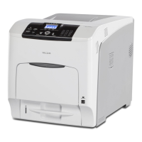
Aficio SP C440DN
Page 223 (By-Pass Feed Roller, Friction Pad)
Ricoh Aficio SP C440DN - By-Pass Feed Roller, Friction Pad
654 pages
Manual
To Next Page
To Next Page
To Previous Page
To Previous Page
Loading...
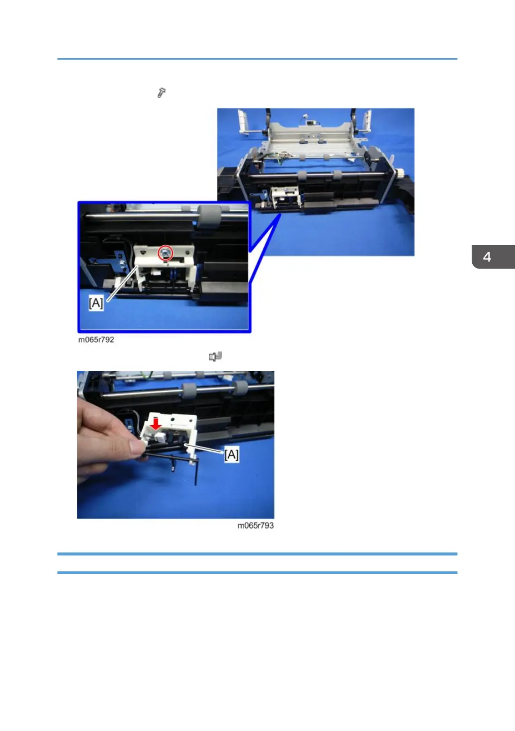
3.
Sensor holder [A] (
x 1)
4.
By-pass paper end sensor [A] (
x 1, hooks)
By-pass Feed Roller, Friction Pad
1.
Duplex unit (
page 208
)
2.
Duplex/By-pass motor bracket with the frame (
page 216 "Duplex/By-pass Motor"
)
Duplex Unit
221
222
224
Table of Contents
Main Page
Section 1
12
Important Safety Notices
3
Responsibilities of the Customer Engineer
3
Customer Engineer
3
Reference Material for Maintenance
3
Before Installation, Maintenance
3
Shipping and Moving the Machine
3
Power
3
Installation, Disassembly, and Adjustments
4
Special Tools
4
During Maintenance
4
General
4
Safety Devices
5
Organic Cleaners
5
Lithium Batteries
5
Disposal of Used Items
6
After Installation, Servicing
6
Power Plug and Power Cord
6
Points to Confirm with Operators
7
Special Safety Instructions for Toner
7
Accidental Physical Exposure
7
Handling and Storing Toner
8
Toner Disposal
8
Safety Instructions for this Machine
8
Prevention of Physical Injury
8
Safety and Ecological Notes for Disposal
9
Health Safety Conditions
9
Observance of Electrical Safety Standards
9
Laser Safety
10
Symbols, Abbreviations and Trademarks
11
Trademarks
11
Table of Contents
12
Product Information
23
Specifications
23
Machine Configuration
24
Different Points from Previous Products
25
Guidance for those Familiar with Predecessor Products
25
Overview
26
Mechanical Component Layout
26
Paper Path
27
Drive Layout
28
Installation
31
Installation Requirements
31
Environment
31
Machine Level
32
Machine Space Requirements
32
Power Requirements
33
Optional Unit Combinations
34
Machine Options
34
Controller Options
34
Printer Installation
35
Installation Procedure
35
Unpacking
35
Installing the Toner
39
Loading Paper
40
Turning Power on
42
Selecting the Panel Display Language
43
Printing the Test Page
44
Settings Relevant to the Service Contract
44
Meter Click Charge
44
Moving the Machine
47
Transporting the Machine
47
Paper Feed Unit (M384)
48
Caster Table (M393)
50
Accessory Check
50
Installation Procedure
51
For Installing the Caster Table (M393) Only
51
For Installing with the Paper Feed Unit (M384)
55
Tray Heater
59
Component Check
59
Tray Heater (Mainframe)
60
Tray Heater (Optional Unit)
64
Component Check
64
For Installing the Tray Heater in M384
65
For Installing the Securing Bracket
71
Controller Options
74
Overview
74
I/F Card Slots
74
Component Check
75
Installation Procedure for USB Device Server Option Type M12
75
SD Card Slots
75
Interface Board Surface
76
Installation Procedure
76
What Do the LED Indications Mean
80
IP Address Setting
81
SD Card Appli Move
82
Overview
82
Outline of SD Card Appli Move
82
Move Exec
83
Undo Exec
84
Preventive Maintenance
85
Maintenance Tables
85
Replacement and Adjustment
87
Notes on the Main Power Switch
87
Push Switch
87
Characteristics of the Push Switch (DC Switch)
87
Shutdown Method
88
Forced Shutdown
88
Before You Start
89
Special Tools
90
Tools
90
Exterior Covers
91
Left Cover
91
Right Cover
92
Rear Cover
93
When Reinstalling the Rear Cover
93
Top Cover
94
When Reinstalling the Top Cover
95
Operation Panel
95
Inner Left Upper Cover
96
Inner Left Front Cover
97
Inner Left Rear Cover
98
Inner Left Lower Cover
98
Inner Right Front Cover
99
Inner Right Rear Cover
101
Laser Optics
102
Caution Decal Locations
102
Laser Unit
102
Before Removing the Old Laser Unit
102
Recovery Procedure for no Replacement Preparation of Laser Unit
103
Removing the Laser Unit
103
After Installing a New Laser Unit
104
When Installing the Laser Unit Fan
106
Laser Unit Fan
106
LDU Shutter Motor
107
Image Creation
108
PCDU (Photo Conductor and Development Unit)
108
When Installing a New PCDU
109
Waste Toner Bottle
112
Toner Supply Tube
113
Toner Supply Motor
119
Toner Collection Motor
120
Waste Toner Bottle Full Sensor
122
Waste Toner Bottle Set Sensor
122
RFID CPU Board
123
RFID Board
124
Development Fan
125
When Installing the Development Fan
126
Image Transfer
127
ITB (Image Transfer Belt) Unit
127
Image Transfer Belt
129
When Installing the Image Transfer Belt
134
ITB Contact Motor
135
ITB Contact Sensor
136
ID Sensor Board
138
After Installing a New ID Sensor Board
140
Paper Transfer
142
PTR (Paper Transfer Roller) Unit
142
When Installing the PTR Unit
142
PTR Contact Motor
143
PTR Contact Sensor
144
Temperature/Humidity Sensor
145
Drive Unit
147
Gear Unit
147
When Installing the Gear Unit
153
Toner Supply Fan
153
Drum Motor: CMY
154
When Installing the Toner Supply Fan
154
Toner Supply Fan Base
154
Development Motor: CMY
155
ITB Unit/ Drum-K/ Development-K Motor
156
Development Clutch: K
156
Fusing/Paper Exit Motor
157
Front Door Sensor
157
Motors with Bracket
158
Registration Motor
160
Paper Feed Motor
161
Vertical Transport Motor
162
Drum Phase Sensor: CMY
163
Drum Phase Sensor: K
163
Drive Unit Fan
164
When Installing the Drive Unit Fan
165
When Installing the Fusing Unit
166
Cleaning Unit
166
Fusing Unit
166
Fusing
166
Pressure Roller Fusing Lamp
167
Pressure Roller
170
When Reinstalling the Pressure Roller
172
Heating Roller Fusing Lamp
172
Fusing Belt
177
When Reinstalling the Fusing Roller
179
Fusing, Heating and Tension Roller
179
Heating Roller Thermostat
180
Heating Roller Thermistor
181
Pressure Roller Thermistor
182
Pressure Roller Thermostat
183
Thermopile
183
Paper Feed
185
Separation Roller
185
Pick-Up and Paper Feed Rollers
185
Paper Feed Unit
186
Registration Sensor
188
Vertical Transport Sensor
189
Paper Height Sensor 1
190
Paper Height Sensor 2
191
Paper Lift Sensor
192
Paper End Sensor
193
Paper Feed Sensor
194
Tray Lift Motor
196
Tray 1 Set Sensor
197
Paper Size Sensor Board
199
Cleaning the Paper Dust Container
199
Paper Exit
200
Paper Exit Unit
200
Paper Exit Sensor
202
Inverter Sensor
205
Paper Overflow Sensor
206
Fusing Exit Sensor
207
Fusing Cooling Fan
208
Inverter Motor
208
When Installing the Fusing Cooling Fan
209
Upper Cover Sensor
209
Duplex Unit
210
By-Pass Tray Unit
212
Duplex Entrance Sensor
214
Duplex Exit Sensor
216
Fusing Entrance Sensor
217
Duplex/By-Pass Motor
218
By-Pass Paper End Sensor
222
By-Pass Feed Roller, Friction Pad
223
Hvps: D
226
Fusing Fan
227
When Installing the Fusing Fan
228
Electrical Components
229
Boards
229
HDD (Option)
231
Disposal of HDD Units
232
Reinstallation
233
Controller Board
233
When Installing the New Controller Board
234
Bridge Board
235
Psu
236
Controller Box
237
Bcu
240
When Installing the New BCU
241
Removing the BCU with Bracket
242
HVPS: T1T2 Board
243
HVPS: CB Board
244
DC Switch Board
246
NVRAM Replacement Procedure
247
NVRAM on the BCU
247
NVRAM on the Controller
248
Summary
250
Gamma Adjustment
250
Adjustments
250
Adjustment Procedure
252
System Maintenance Reference
255
Service Program Mode
255
Service Mode Operation
255
Accessing the Required Program
255
Inputting a Value or Setting for a Service Program
255
Exiting Service Mode
255
Remarks
256
Display on the Control Panel Screen
256
Bit Switch Programming
258
Service SP Mode Tables
260
SP1-XXX (Service Mode)
260
Engine SP Mode Tables: SP1000
273
SP1-XXX (Feed)
273
Engine SP Mode Tables - SP2000
299
SP2-XXX (Drum)
299
Engine SP Mode Tables - SP3000
399
SP3-XXX (Process)
399
Section 2
639
Appendix: Specifications
641
General Specifications
641
Specifications
641
Supported Paper Sizes
644
Software Accessories
646
Utility Software
646
Optional Equipment
647
Paper Feed Unit (M384)
647
Appendix: Preventive Maintenance Tables
649
Maintenance Tables
649
Preventive Maintenance Items
649
User Maintenance
649
Service Maintenance
650
Optional Units
651
Paper Feed Unit
651
Related product manuals
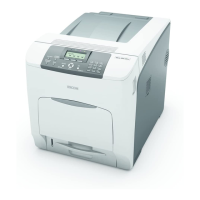
Ricoh Aficio SP C430DN
260 pages
Ricoh Aficio SP C431DN
58 pages
Ricoh Aficio SP C311N
306 pages
Ricoh Aficio SP C231N
152 pages
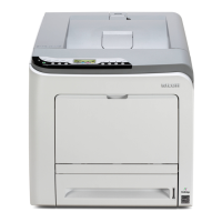
Ricoh Aficio SP C320DN
260 pages
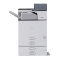
Ricoh Aficio SP C840DN
328 pages
Ricoh Aficio SP C242DN
172 pages
Ricoh Aficio SP C820DN
288 pages
Ricoh Aficio SP C232DN
288 pages
Ricoh Aficio SP C730DN
100 pages
Ricoh Aficio SP C811DN
384 pages
Ricoh Aficio SP 5200DN
824 pages