CH EDIT Window
105
Memo
The isolation point for the key-in signal is as follows.
Key-in signal Isolation point
SELF Signal input to Dynamics
Input channel CH TOP
Output bus POST FADER
Memo
With MAIN, only SELF can be selected for the key-in signal.
MEMO
The level detection points for INPUT METER, OUTPUT METER,
and GR METER are as follows.
HPF
LPF
INS
A
DYN/EQ
or
EQ/DYN
4-BAND
EQ
INS
B
INPUT
METER
(PRE DYN)
DYN 1
OUTPUT
METER
(POST DYN)
GR
INPUT
METER
(PRE DYN)
DYN 2
OUTPUT
METER
(POST DYN)
GR
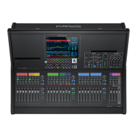
Parameter Area of the DYNAMICS Tab
The parameters displayed in the parameter area of the DYNAMICS
tab dier according to the Dynamics type.
EXPANDER
THRESHOLD Threshold
RATIO Ratio
ATTACK Attack Time
RELEASE Release Time
KNEE
Knee
5 HARD
5 SOFT 1-9
KEY HPF HPF center frequency for the key-in lter
ON Turns key-in lter on/o.
KEY LPF LPF center frequency for the key-in lter
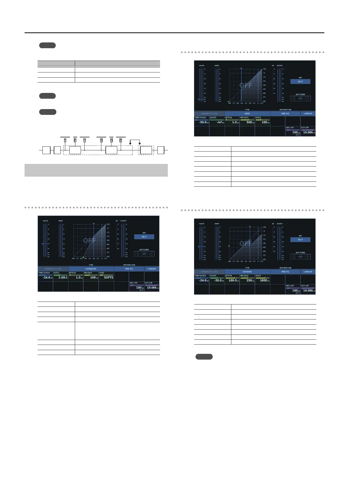
GATE
THRESHOLD Threshold
RANGE Range
ATTACK Attack Time
RELEASE Release Time
HOLD Hold Time
KEY HPF HPF center frequency for the key-in lter
ON Turns key-in lter on/o.
KEY LPF LPF center frequency for the key-in lter
DUCKING
THRESHOLD Threshold
RANGE Range
ATTACK Attack Time
RELEASE Release Time
HOLD Hold Time
KEY HPF HPF center frequency for the key-in lter
ON Turns key-in lter on/o.
KEY LPF LPF center frequency for the key-in lter
MEMO
When the key-in signal is set to an input channel
(other than SELF), fader values and muting are applied to the
key-in signal.
 Loading...