D.29
Date Code 20080918 Instruction Manual SEL-749M Relay
Modbus RTU Communications Protocol
Modbus Register Map
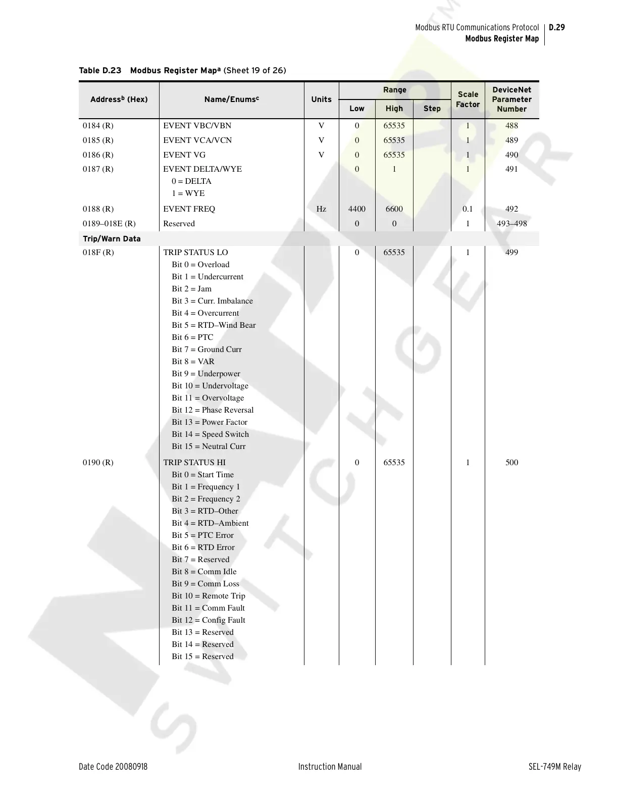
0184 (R) EVENT VBC/VBN V 0 65535 1 488
0185 (R) EVENT VCA/VCN V 0 65535 1 489
0186 (R) EVENT VG V 0 65535 1 490
0187 (R) EVENT DELTA/WYE
0 = DELTA
1 = WYE
01 1 491
0188 (R) EVENT FREQ Hz 4400 6600 0.1 492
0189–018E (R) Reserved 0 0 1 493–498
Trip/Warn Data
018F (R) TRIP STATUS LO
Bit 0 = Overload
Bit 1 = Undercurrent
Bit 2 = Jam
Bit 3 = Curr. Imbalance
Bit 4 = Overcurrent
Bit 5 = RTD–Wind Bear
Bit 6 = PTC
Bit 7 = Ground Curr
Bit 8 = VAR
Bit 9 = Underpower
Bit 10 = Undervoltage
Bit 11 = Overvoltage
Bit 12 = Phase Reversal
Bit 13 = Power Factor
Bit 14 = Speed Switch
Bit 15 = Neutral Curr
0 65535 1 499
0190 (R) TRIP STATUS HI
Bit 0 = Start Time
Bit 1 = Frequency 1
Bit 2 = Frequency 2
Bit 3 = RTD–Other
Bit 4 = RTD–Ambient
Bit 5 = PTC Error
Bit 6 = RTD Error
Bit 7 = Reserved
Bit 8 = Comm Idle
Bit 9 = Comm Loss
Bit 10 = Remote Trip
Bit 11 = Comm Fault
Bit 12 = Config Fault
Bit 13 = Reserved
Bit 14 = Reserved
Bit 15 = Reserved
0 65535 1 500
Table D.23 Modbus Register Map
a
(Sheet 19 of 26)
Address
b
(Hex) Name/Enums
c
Units
Range
Scale
Fa c tor
DeviceNet
Parameter
Number
Low High Step
Courtesy of NationalSwitchgear.com
 Loading...


