D.30
SEL-749M Relay Instruction Manual Date Code 20080918
Modbus RTU Communications Protocol
Modbus Register Map
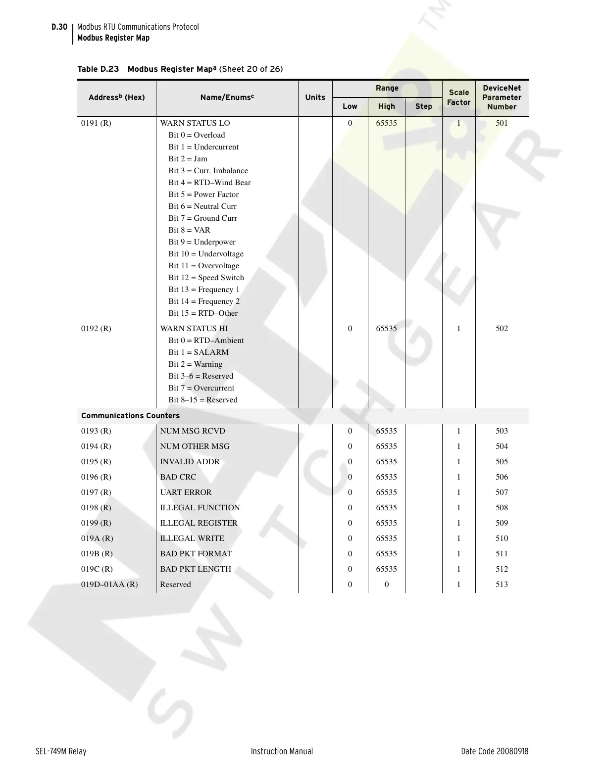
0191 (R) WARN STATUS LO
Bit 0 = Overload
Bit 1 = Undercurrent
Bit 2 = Jam
Bit 3 = Curr. Imbalance
Bit 4 = RTD–Wind Bear
Bit 5 = Power Factor
Bit 6 = Neutral Curr
Bit 7 = Ground Curr
Bit 8 = VAR
Bit 9 = Underpower
Bit 10 = Undervoltage
Bit 11 = Overvoltage
Bit 12 = Speed Switch
Bit 13 = Frequency 1
Bit 14 = Frequency 2
Bit 15 = RTD–Other
0 65535 1 501
0192 (R) WARN STATUS HI
Bit 0 = RTD–Ambient
Bit 1 = SALARM
Bit 2 = Warning
Bit 3–6 = Reserved
Bit 7 = Overcurrent
Bit 8–15 = Reserved
0 65535 1 502
Communications Counters
0193 (R) NUM MSG RCVD 0 65535 1 503
0194 (R) NUM OTHER MSG 0 65535 1 504
0195 (R) INVALID ADDR 0 65535 1 505
0196 (R) BAD CRC 0 65535 1 506
0197 (R) UART ERROR 0 65535 1 507
0198 (R) ILLEGAL FUNCTION 0 65535 1 508
0199 (R) ILLEGAL REGISTER 0 65535 1 509
019A (R) ILLEGAL WRITE 0 65535 1 510
019B (R) BAD PKT FORMAT 0 65535 1 511
019C (R) BAD PKT LENGTH 0 65535 1 512
019D–01AA (R) Reserved 0 0 1 513
Table D.23 Modbus Register Map
a
(Sheet 20 of 26)
Address
b
(Hex) Name/Enums
c
Units
Range
Scale
Fa c tor
DeviceNet
Parameter
Number
Low High Step
Courtesy of NationalSwitchgear.com
 Loading...


