G.3
Date Code 20080918 Instruction Manual SEL-749M Relay
Relay Word Bits
Definitions
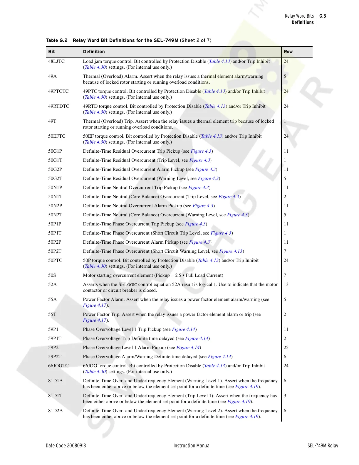
48LJTC Load jam torque control. Bit controlled by Protection Disable (Table 4.13) and/or Trip Inhibit
(Table 4.30) settings. (For internal use only.)
24
49A Thermal (Overload) Alarm. Assert when the relay issues a thermal element alarm/warning
because of locked rotor starting or running overload conditions.
5
49PTCTC 49PTC torque control. Bit controlled by Protection Disable (Table 4.13) and/or Trip Inhibit
(Table 4.30) settings. (For internal use only.)
24
49RTDTC 49RTD torque control. Bit controlled by Protection Disable (Table 4.13) and/or Trip Inhibit
(Table 4.30) settings. (For internal use only.)
24
49T Thermal (Overload) Trip. Assert when the relay issues a thermal element trip because of locked
rotor starting or running overload conditions.
1
50EFTC 50EF torque control. Bit controlled by Protection Disable (Table 4.13) and/or Trip Inhibit
(Table 4.30) settings. (For internal use only.)
24
50G1P Definite-Time Residual Overcurrent Trip Pickup (see Figure 4.3)11
50G1T Definite-Time Residual Overcurrent (Trip Level, see Figure 4.3)1
50G2P Definite-Time Residual Overcurrent Alarm Pickup (see Figure 4.3)11
50G2T Definite-Time Residual Overcurrent (Warning Level, see Figure 4.3)5
50N1P Definite-Time Neutral Overcurrent Trip Pickup (see Figure 4.3)11
50N1T Definite-Time Neutral (Core Balance) Overcurrent (Trip Level, see Figure 4.3)2
50N2P Definite-Time Neutral Overcurrent Alarm Pickup (see Figure 4.3)11
50N2T Definite-Time Neutral (Core Balance) Overcurrent (Warning Level, see Figure 4.3)5
50P1P Definite-Time Phase Overcurrent Trip Pickup (see Figure 4.3)11
50P1T Definite-Time Phase Overcurrent (Short Circuit Trip Level, see Figure 4.3)1
50P2P Definite-Time Phase Overcurrent Alarm Pickup (see Figure 4.3)11
50P2T Definite-Time Phase Overcurrent (Short Circuit Warning Level, see Figure 4.13)7
50PTC 50P torque control. Bit controlled by Protection Disable (Table 4.13) and/or Trip Inhibit
(Table 4.30) settings. (For internal use only.)
24
50S Motor starting overcurrent element (Pickup = 2.5 • Full Load Current) 7
52A Asserts when the SEL
OGIC control equation 52A result is logical 1. Use to indicate that the motor
contactor or circuit breaker is closed.
13
55A Power Factor Alarm. Assert when the relay issues a power factor element alarm/warning (see
Figure 4.17).
5
55T Power Factor Trip. Assert when the relay issues a power factor element alarm or trip (see
Figure 4.17).
2
59P1 Phase Overvoltage Level 1 Trip Pickup (see Figure 4.14)11
59P1T Phase Overvoltage Trip Definite time delayed (see Figure 4.14)2
59P2 Phase Overvoltage Level 1 Alarm Pickup (see Figure 4.14)25
59P2T Phase Overvoltage Alarm/Warning Definite time delayed (see Figure 4.14)6
66JOGTC 66JOG torque control. Bit controlled by Protection Disable (Table 4.13) and/or Trip Inhibit
(Table 4.30) settings. (For internal use only.)
24
81D1A Definite-Time Over- and Underfrequency Element (Warning Level 1). Assert when the frequency
has been either above or below the element set point for a definite time (see Figure 4.19).
6
81D1T Definite-Time Over- and Underfrequency Element (Trip Level 1). Assert when the frequency has
been either above or below the element set point for a definite time (see Figure 4.19).
3
81D2A Definite-Time Over- and Underfrequency Element (Warning Level 2). Assert when the frequency
has been either above or below the element set point for a definite time (see Figure 4.19).
6
Table G.2 Relay Word Bit Definitions for the SEL-749M (Sheet 2 of 7)
Bit Definition Row
Courtesy of NationalSwitchgear.com
 Loading...


