G.4
SEL-749M Relay Instruction Manual Date Code 20080918
Relay Word Bits
Definitions
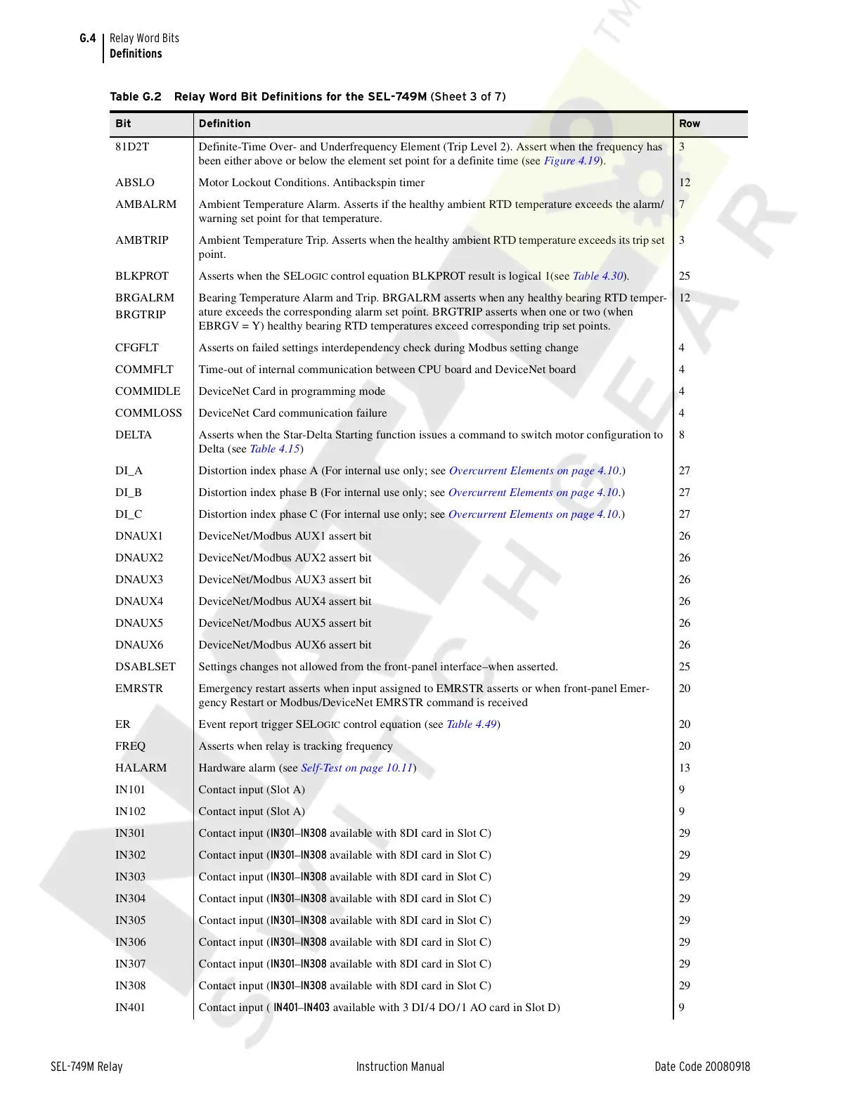
81D2T Definite-Time Over- and Underfrequency Element (Trip Level 2). Assert when the frequency has
been either above or below the element set point for a definite time (see Figure 4.19).
3
ABSLO Motor Lockout Conditions. Antibackspin timer 12
AMBALRM Ambient Temperature Alarm. Asserts if the healthy ambient RTD temperature exceeds the alarm/
warning set point for that temperature.
7
AMBTRIP Ambient Temperature Trip. Asserts when the healthy ambient RTD temperature exceeds its trip set
point.
3
BLKPROT Asserts when the SEL
OGIC control equation BLKPROT result is logical 1(see Table 4.30). 25
BRGALRM
BRGTRIP
Bearing Temperature Alarm and Trip. BRGALRM asserts when any healthy bearing RTD temper-
ature exceeds the corresponding alarm set point. BRGTRIP asserts when one or two (when
EBRGV = Y) healthy bearing RTD temperatures exceed corresponding trip set points.
12
CFGFLT Asserts on failed settings interdependency check during Modbus setting change 4
COMMFLT Time-out of internal communication between CPU board and DeviceNet board 4
COMMIDLE DeviceNet Card in programming mode 4
COMMLOSS DeviceNet Card communication failure 4
DELTA Asserts when the Star-Delta Starting function issues a command to switch motor configuration to
Delta (see Table 4.15)
8
DI_A Distortion index phase A (For internal use only; see Overcurrent Elements on page 4.10.) 27
DI_B Distortion index phase B (For internal use only; see Overcurrent Elements on page 4.10.) 27
DI_C Distortion index phase C (For internal use only; see Overcurrent Elements on page 4.10.) 27
DNAUX1 DeviceNet/Modbus AUX1 assert bit 26
DNAUX2 DeviceNet/Modbus AUX2 assert bit 26
DNAUX3 DeviceNet/Modbus AUX3 assert bit 26
DNAUX4 DeviceNet/Modbus AUX4 assert bit 26
DNAUX5 DeviceNet/Modbus AUX5 assert bit 26
DNAUX6 DeviceNet/Modbus AUX6 assert bit 26
DSABLSET Settings changes not allowed from the front-panel interface–when asserted. 25
EMRSTR Emergency restart asserts when input assigned to EMRSTR asserts or when front-panel Emer-
gency Restart or Modbus/DeviceNet EMRSTR command is received
20
ER Event report trigger SEL
OGIC control equation (see Table 4.49)20
FREQ Asserts when relay is tracking frequency 20
HALARM Hardware alarm (see Self-Test on page 10.11)13
IN101 Contact input (Slot A) 9
IN102 Contact input (Slot A) 9
IN301 Contact input (IN301–IN308 available with 8DI card in Slot C) 29
IN302 Contact input (IN301–IN308 available with 8DI card in Slot C) 29
IN303 Contact input (IN301–IN308 available with 8DI card in Slot C) 29
IN304 Contact input (IN301–IN308 available with 8DI card in Slot C) 29
IN305 Contact input (IN301–IN308 available with 8DI card in Slot C) 29
IN306 Contact input (IN301–IN308 available with 8DI card in Slot C) 29
IN307 Contact input (IN301–IN308 available with 8DI card in Slot C) 29
IN308 Contact input (IN301–IN308 available with 8DI card in Slot C) 29
IN401 Contact input ( IN401–IN403 available with 3 DI/4 DO/1 AO card in Slot D) 9
Table G.2 Relay Word Bit Definitions for the SEL-749M (Sheet 3 of 7)
Bit Definition Row
Courtesy of NationalSwitchgear.com
 Loading...


