4.21
Date Code 20080918 Instruction Manual SEL-749M Relay
Protection and Logic Functions
PTC/RTD-Based Protection
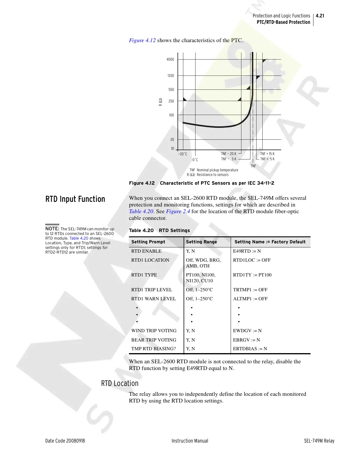
Figure 4.12 shows the characteristics of the PTC.
Figure 4.12 Characteristic of PTC Sensors as per IEC 34-11-2
RTD Input Function
When you connect an SEL-2600 RTD module, the SEL-749M offers several
protection and monitoring functions, settings for which are described in
Table 4.20. See Figure 2.4 for the location of the RTD module fiber-optic
cable connector.
NOTE: The SEL-749M can monitor up
to 12 RTDs connected to an SEL-2600
RTD module. Ta bl e 4. 20 shows
Location, Type, and Trip/Warn Level
settings only for RTD1; settings for
RTD2–RTD12 are similar.
When an SEL-2600 RTD module is not connected to the relay, disable the
RTD function by setting E49RTD equal to N.
RTD Location
The relay allows you to independently define the location of each monitored
RTD by using the RTD location settings.
4000
1330
550
250
100
20
10
—20˚C
0˚C
TNF
TNF
R (
Ω
)
Nominal pickup temperature
Resistance to sensors
TNF — 20 K
TNF — 5 K
TNF + 15 K
TNF + 5 K
R (Ω)
Table 4.20 RTD Settings
Setting Prompt Setting Range Setting Name := Factory Default
RTD ENABLE Y, N E49RTD := N
RTD1 LOCATION Off, WDG, BRG,
AMB, OTH
RTD1LOC := OFF
RTD1 TYPE PT100, NI100,
NI120, CU10
RTD1TY := PT100
RTD1 TRIP LEVEL Off, 1–250°C TRTMP1 := OFF
RTD1 WARN LEVEL Off, 1–250°C ALTMP1 := OFF
•
•
•
•
•
•
•
•
•
WIND TRIP VOTING Y, N EWDGV := N
BEAR TRIP VOTING Y, N EBRGV := N
TMP RTD BIASING? Y, N ERTDBIAS := N
Courtesy of NationalSwitchgear.com