Chapter 3 Operating Instructions
Flexi Classic Gateways
26 © SICK AG • Industrial Safety Systems • Germany • All rights reserved 8011834/YT28/2016-03-15
Subject to change without notice
Flexi Classic gateways
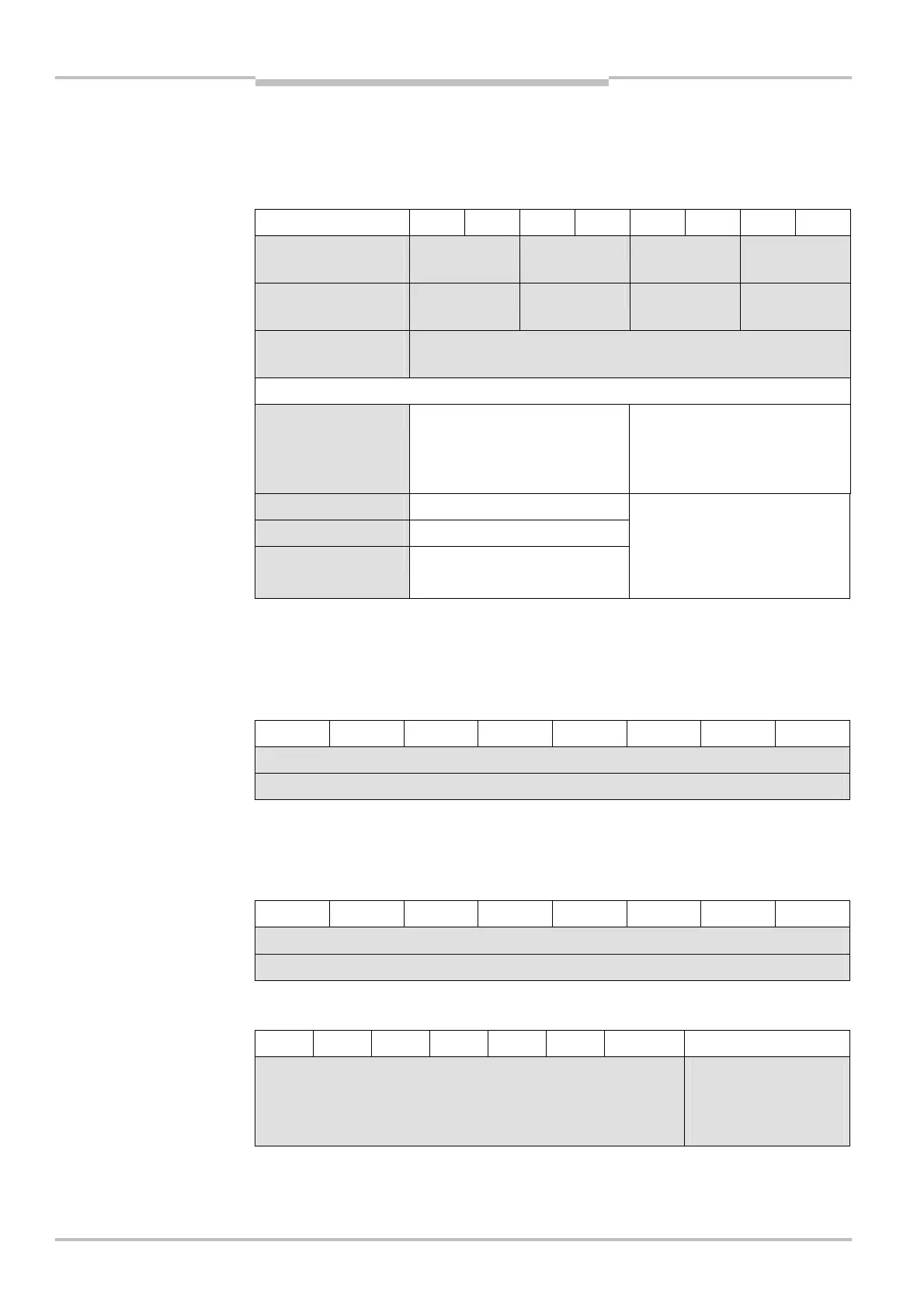
3.2.20 KONF
Configuration setting for the selected Flexi Classic module (not UE410-GU). On a UE410-
8DI and UE410-MDI this byte is set to zero, as apart from the input circuit functions there
a
re no other configuration options.
Bit 7 6 5 4 3 2 1 Bit 0
UE410-MU
UE410-XU
T S3 S2 S1
UE410-MM
UE410-XM
– – – S1
UE410-8DI
UE410-MDI
–
T Time variant UE410-MU. UE410-
MU are supplied in three time
variants. The time variant defines
the reactivation delay.
11 = Factor 1 s
10 = Factor 10 s
01 = Factor 1 min
S1 Configuration jumper on S1
S2 Configuration jumper on S2
S3 Configuration jumper on S3
00 = Open
01 = Connected to X1
10 = Connected to X2
11 = Connected to +U
B
3.2.21 CRC_H CODE and CRC_L CODE
High byte/low byte for the 16-bit checksum via the code area on the selected Flexi Classic
module.
Bit 7 6 5 4 3 2 1 Bit 0
CRC_H CODE
CRC_L CODE
3.2.22 DIAG-VERSION_H and DIAG-VERSION_L
High byte/low byte for the software version on the selected UE410-PRO/UE410-DEV.
The software version is supplied as a 16-bit-hex number, e.g. 0624 = 2006, week 24.
Bit 7 6 5 4 3 2 1 Bit 0
DIAG-VERSION_H
DIAG-VERSION_L
3.2.23 System interface status (only UE410-EN3)
Bit 7 6 5 4 3 2 1 Bit 0
–
0= Flex bus
communication OK
1= Flex bus
communication faulty
CRC_L CODE
and DIAG-VERSION_L
status (only UE410-EN3)