117
8024638/AE00/V1-0/2019-09| SICK S E R V I C E M A N U A L | MCS200HW
Subject to change without notice
REPAIRS 5
9 Insert filter wheel housing 1 into the sender/receiver unit and screw tight.
10 Connect the lug connection of filter wheel housing 1 to the LPMS04 circuit board.
11 Replace the drying agent (see Chapter “Replacing the drying agent”, page 44).
12 Close the sender/receiver unit cover and screw tight.
13 Connect the MCS200HW power supply.
14 Perform optical adjustment (see Chapter “Performing optical adjustment”, page 103).
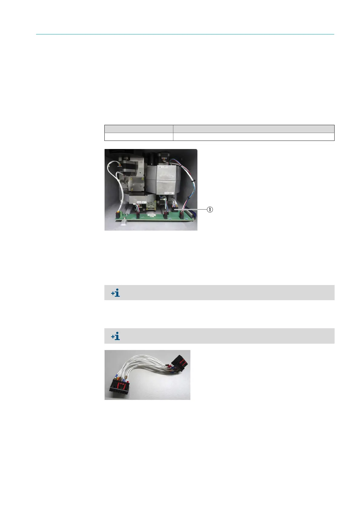
5.3.12 Replacing the LPMS03 detector cable
Fig. 179: LPMS03 Detector cable
1 Disconnect the MCS200HW power supply.
2 Open the sender/receiver unit (see Chapter “Opening the sender/receiver unit”,
page 44).
3 Disconnect the detector cable from the LPMS04 detector circuit board and LPMS03
detector circuit board.
4 Connect a new detector cable.
Fig. 180: Detector cable
5 Replace the drying agent (see Chapter “Replacing the drying agent”, page 44).
6 Close the sender/receiver unit cover and screw tight.
7 Connect the MCS200HW power supply.
Spare parts set No. Contents
2099806 Detector cable
1Detector cable
The drying agent must be replaced each time the sender/receiver unit is opened.
Connectors on both ends of the detector cable are identical.

 Loading...

