54
8024638/AE00/V1-0/2019-09| SICKSERVICE MANUAL | MCS200HW
Subject to change without notice
5 REPAIRS
7 Reconnect the leads.
▸ Lead 1 (Phase) -> L
▸ Lead 2 (neutral conductor) -> N
▸ Middle -> protective conductor (PE)
Fig. 63: Fan, wire slots
8 Fit the red cover cap.
9 Restore the power supply to the door fan.
10 Switch the MCS200HW on.
5.1.2 Replacing the pressure reducer unit
1 Close off instrument air provided by the customer.
2 Loosen the fastening screws behind the pressure reducer unit with a 4 mm Allen key
(4
pieces).
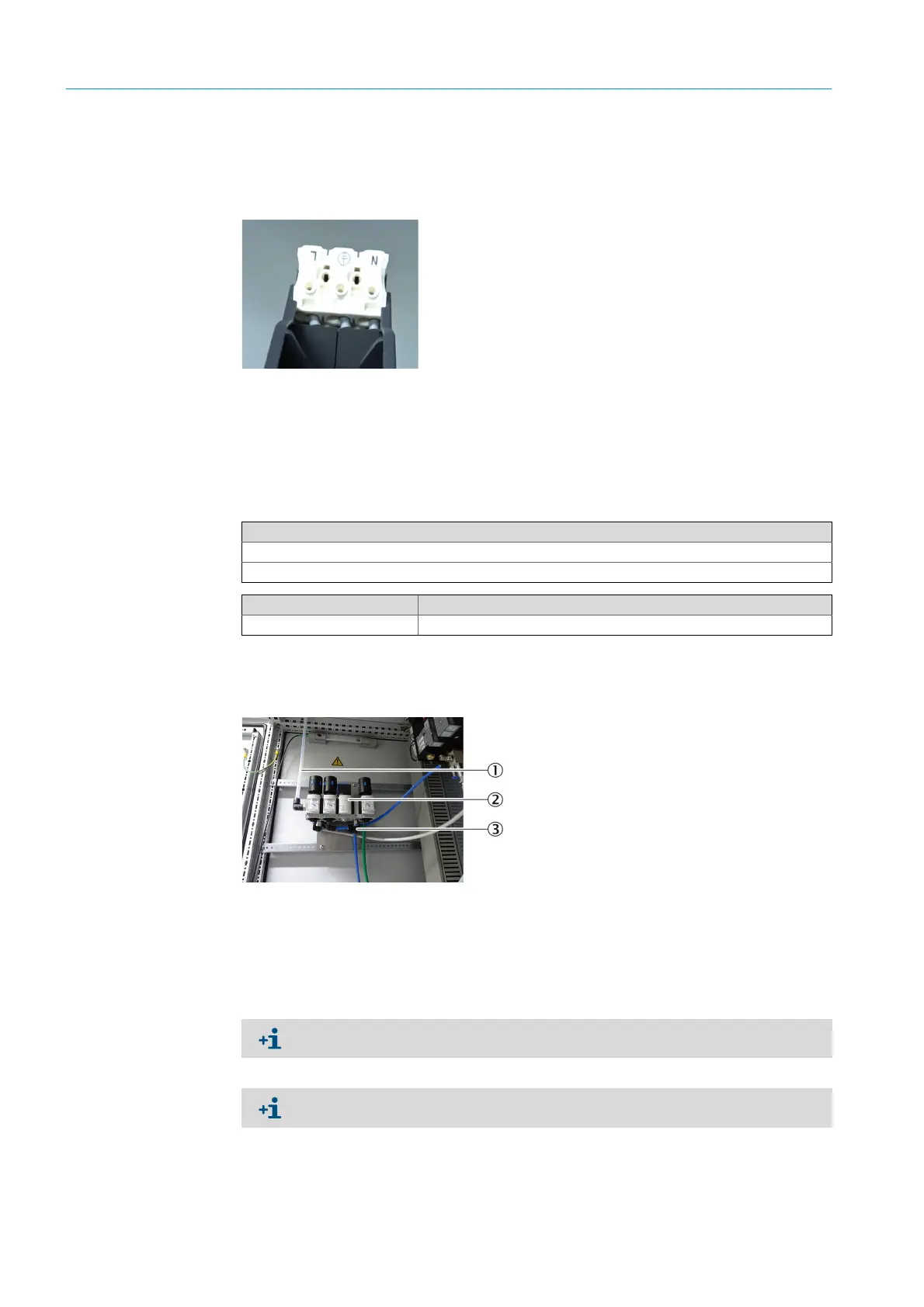
Fig. 64: Pressure reducer unit
3 Disconnect the hose connections.
4 Screw the new pressure reducer unit tight.
Tools required
Phillips screwdriver
4 mm Allen key
Spare parts set No. Contents
5329115 Pressure reducer unit
1Instrument air
2 Pressure reducer module
3 Hose connections
Document or mark the positions of the hose connections before removing.
Blue valve must be open.

 Loading...

