135
8024638/AE00/V1-0/2019-09| SICK S E R V I C E M A N U A L | MCS200HW
Subject to change without notice
REPAIRS 5
8 Place the upper electronics unit with the new LPMS01 on the lower electronics unit.
9 Connect the cables to the lower electronics unit.
10 Screw the upper and lower electronics unit together:
▸ Top fastening screws (2 pieces).
▸ Rear fastening screws (2 pieces).
11 Refit the CPU (see Chapter “Replacing the LINUX CPU”, page 135).
12 Connect the connection cable to the LPMS04.
13 Insert the electronics unit into the device cabinet and screw tight (see Chapter “Remov-
ing and fitting the electronics unit”, page 129).
14 Perform zero point adjustment (see Chapter “Adjusting the zero point”, page 128).
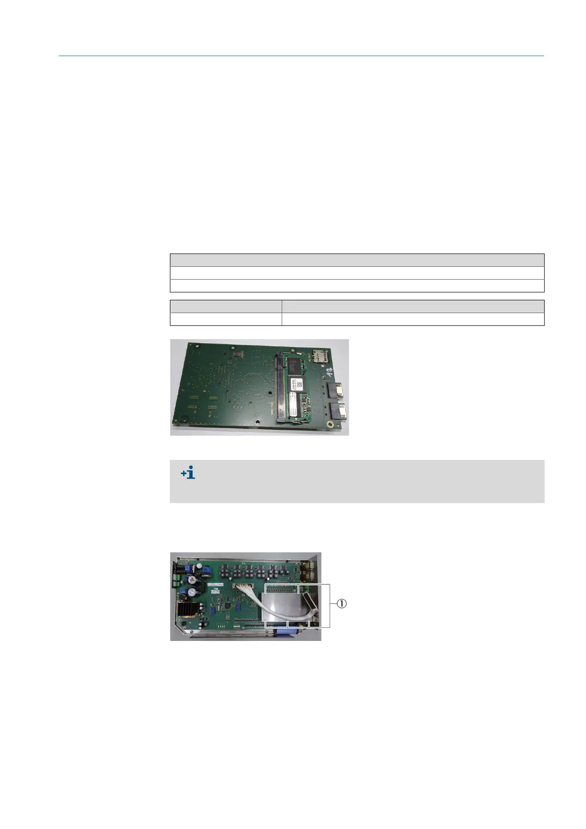
5.4.3 Replacing the LINUX CPU
Fig. 218: Linux CPU
1 Remove the electronics unit (see Chapter “Removing and fitting the electronics unit”,
page 129).
2 Loosen the CPU housing fastening screws with a Phillips screwdriver (5 pieces).
Fig. 220: Linux CPU housing
3 Remove the CPU housing.
4 Loosen the studs with a 5.5 mm socket wrench (5 pieces).
Tools required
Phillips screwdriver
5.5 mm socket wrench
Spare parts set No. Contents
2085767 LINUX CPU
Create a parameter backup with SOPAS when possible:
1
Select
Maintenance
-> ‚
Load/Save Parameter
.
1
Click
Save parameter backup
.
Replace the SD card when a parameter backup cannot be created.
1Screws

 Loading...

